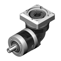
PGIIR series
Right angle planetary- Black coated steel housing, aluminum output and motor adapter flange
- Steel output shaft with or without key
- Spur gear design
- Nominal torques:
- T2N : 8 Nm - 459 Nm
- Ratios
- 1-stage : 3 / 4 / 5 / 7 / 9 / 10
- 2-stage : 12 / 15 / 16 / 20 / 25 / 30 / 35 / 40 / 50 / 70 / 100
- 3-stage : 120 / 160 / 200 / 280 / 350 / 500 / 700 / 1000
- Low backlash
- 1-stage : ≤ 10 ~ 12 arcmin
- 2-stage : ≤ 12 ~ 14 arcmin
- 3-stage : ≤ 14 ~ 16 arcmin
- High efficiency
- 1-stage : ≥ 93%
- 2-stage : ≥ 90%
- 3-stage : ≥ 87%
- Easy mount
- Compact structure
- Sizes available: PGIIR 040 / PGIIR 060 / PGIIR 080 / PGIIR 120 / PGIIR 160
PGIIR |
Stage | Ratio (1) | PGIIR 040 | PGIIR 060 | PGIIR 080 | PGIIR 120 | PGIIR 160 | |
| Nominal output torque T2N | Nm | 1 | 3 | 16 | 42 | 110 | 217 | 430 |
| 4 | 16 | 42 | 113 | 223 | 440 | |||
| 5 | 15 | 40 | 118 | 220 | 435 | |||
| 7 | 12 | 35 | 96 | 198 | 366 | |||
| 9 | 8 | 24 | 60 | 125 | 273 | |||
| 10 | 10 | 27 | 68 | 155 | 295 | |||
| 2 | 12 | 16 | 42 | 110 | 217 | 430 | ||
| 15 | 15 | 40 | 109 | 213 | 424 | |||
| 16 | 16 | 42 | 116 | 228 | 452 | |||
| 20 | 16 | 42 | 116 | 230 | 454 | |||
| 25 | 15 | 40 | 123 | 228 | 450 | |||
| 30 | 15 | 40 | 108 | 212 | 422 | |||
| 35 | 12 | 35 | 100 | 206 | 382 | |||
| 40 | 16 | 43 | 117 | 232 | 459 | |||
| 50 | 15 | 40 | 123 | 228 | 450 | |||
| 70 | 12 | 35 | 100 | 206 | 382 | |||
| 81 | 8 | 24 | 59 | 131 | 285 | |||
| 100 | 10 | 27 | 70 | 162 | 308 | |||
| 3 | 120 | 19 | 50 | 137 | - | - | ||
| 160 | 16 | 43 | 118 | - | - | |||
| 200 | 16 | 43 | 118 | - | - | |||
| 280 | 12 | 35 | 99 | - | - | |||
| 350 | 12 | 35 | 99 | - | - | |||
| 500 | 15 | 40 | 122 | - | - | |||
| 700 | 12 | 35 | 99 | - | - | |||
| 1000 | 10 | 27 | 70 | - | - | |||
| Emergency stop torque T2NOT | Nm | 1,2,3 | 3~1000 | 3 times nominal output torque T2N | ||||
| Max. Acceleration torque T2B | Nm | 1,2,3 | 3~1000 | T2B = 60% van T2NOT | ||||
| No load running torque(2) | Nm | 1 | 3~10 | 0.10 | 0.15 | 0.45 | 0.85 | 2.55 |
| 2 | 12~100 | 0.10 | 0.15 | 0.35 | 0.45 | 0.85 | ||
| 3 | 120~1000 | 0.10 | 0.15 | 0.45 | - | - | ||
| Backlash(3) | arcmin | 1 | 3~10 | ≤12 | ≤11 | ≤10 | ≤10 | ≤10 |
| 2 | 12~100 | ≤14 | ≤13 | ≤12 | ≤12 | ≤12 | ||
| 3 | 120~1000 | ≤16 | ≤15 | ≤14 | - | - | ||
| Torsional rigidity | Nm/arcmin | 1,2,3 | 3~1000 | 0.5 | 2 | 8 | 12 | 16 |
| Nominal input speed n1N | rpm | 1,2,3 | 3~1000 | 4,500 | 4,000 | 3,600 | 3,600 | 2,500 |
| Max. input speed n1B | rpm | 1,2,3 | 3~1000 | 8,000 | 6,000 | 6,000 | 4,800 | 3,600 |
| Max. radial load F2rB (4) | N | 1,2,3 | 3~1000 | 520 | 1,030 | 1,570 | 3,590 | 4,690 |
| Max. axial load F2aB (4) | N | 1,2,3 | 3~1000 | 260 | 515 | 785 | 1,795 | 2,345 |
| Max. tilting moment M2k | Nm | 1,2 | 3~100 | 10 | 35 | 55 | 170 | 300 |
| Operating temperature | °C | 1,2,3 | 3~1000 | 0°C ~ +90°C | ||||
| Degree of Protection | 1,2,3 | 3~1000 | IP65 | |||||
| Lubrication | 1,2,3 | 3~1000 | Synthetisch lubrication grease | |||||
| Mounting position | 1,2,3 | 3~1000 | All directions | |||||
| Running noise (2) | dB (A) | 1,2,3 | 3~1000 | ≤70 | ≤72 | ≤74 | ≤75 | ≤77 |
| Max. bending moment based on input flange Mb (5) | Nm | 1,2,3 | 3~1000 | 3 | 6 | 10 | 17 | 19 |
| Efficiency n | % | 1 | 3~10 | ≥93% | ||||
| 2 | 12~100 | ≥90% | ||||||
| 3 | 120~1000 | ≥87% | ||||||
- Ratio ( i = N in / N out )
- These values are measured by gearbox with ratio 10 (1-stage) or ratio 100 (2-stage) at 3.000 rpm no loading.
By lower ratio and/or higher RPM, the noise level could be 3 to 5 dB higher - Backlash is measured at 2% of Nominal output torque T2N.
- Applied to the ourput flange center at 100 rpm.
- Max. motor weight* (kg) = (0.1 x Mb) / (motor length (m))
*with symmetrically distributed motor weight
*with horizontal and stationary mounting
Permitted Radial And Axial Loads
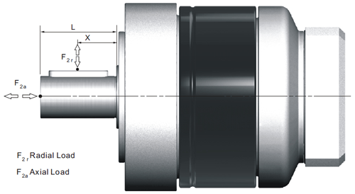
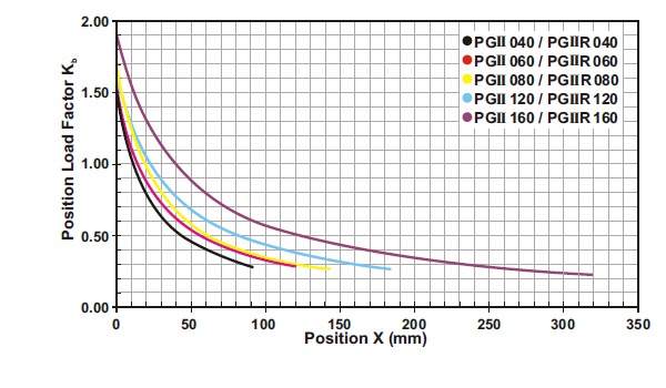
If radial force F2r is not exerted on the center of the ouput shaft X < ½ x L or X > ½ x L, the permitted radial and axial loads can be calculated by the position load factor Kb on the above diagram.
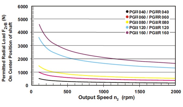
Permitted radial load F2r on center of output shaft X = ½ x L for various output speeds.
(A) Ø Input shaft diameter
(B) Permitted loading values on the output shaft. Please contact Apex Dynamics for more details.
| Model No. | PGIIR 040 | PGIIR 060 | PGIIR 080 | PGIIR 120 | PGIIR 160 | |||||||||
| Ø (A) (C3) | 1-stage | 2-stage | 3-stage | 1-stage | 2-stage | 3-stage | 1-stage | 2-stage | 3-stage | 1-stage | 2-stage | 1-stage | 2-stage | |
| 8 |
kg*cm2 |
0.18 | 0.18 | 0.18 | 0.36 | 0.36 | 0.36 | - | - | - | - | - | - | - |
| 11 | 0.20 | 0.20 | 0.20 | 0.39 | 0.39 | 0.39 | - | - | - | - | - | - | - | |
| 14 | - | - | 0.24 | 0.43 | 0.43 | 0.43 | 1.87 | 1.87 | 1.87 | - | - | - | - | |
| 19 | - | - | - | 1.24 | 1.24 | 1.24 | 2.67 | 2.67 | 2.67 | 6.80 | 6.80 | - | 13.57 | |
| 24 | - | - | - | - | - | - | 2.97 | 2.97 | 2.97 | 7.10 | 7.10 | 13.87 | 13.87 | |
| 28 | - | - | - | - | - | - | 3.47 | 3.47 | 3.47 | 7.59 | 7.59 | 14.36 | 14.36 | |
| 32 | - | - | - | - | - | - | - | - | - | 10.56 | 10.56 | 17.33 | 17.33 | |
| 35 | - | - | - | - | - | - | - | - | - | 11.97 | 11.97 | 18.74 | 18.74 | |
| 38 | - | - | - | - | - | - | - | - | - | 13.95 | 13.95 | 20.79 | 20.79 | |
| 42 | - | - | - | - | - | - | - | - | - | - | - | 26.54 | - | |
(A) ø = Input shaft diameter
PGIIR series
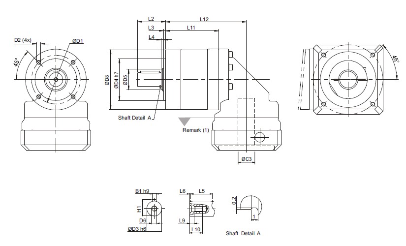
| Dimension | PGIIR 040 | PGIIR 060 | PGIIR 080 | PGIIR 120 | PGIIR 160 | ||||||||
| 1-stage | 2-stage | 3-stage | 1-stage | 2-stage | 3-stage | 1-stage | 2-stage | 3-stage | 1-stage | 2-stage | 1-stage | 2-stage | |
| D1 | 34 | 62 | 70 | 100 | 145 | ||||||||
| D2 | M4 x 9 | M5 x 10 | M6 x 12 | M10 x 18 | M12 x 22 | ||||||||
| D3 h6 | 10 | 14 | 20 | 25 | 40 | ||||||||
| D4 h7 | 26 | 40 | 60 | 80 | 130 | ||||||||
| D5 | 17 | 17 | 30 | 40 | 55 | ||||||||
| D6 | M3 x 0.5P | M5 x 0.8P | M6 x 1P | M10 x 1.5P | M16 x 2P | ||||||||
| D8 | 44 | 60 | 86 | 114 | 160 | ||||||||
| L2 | 26 | 35 | 40 | 55 | 87 | ||||||||
| L3 | 2 | 3 | 3 | 4 | 5 | ||||||||
| L4 | 1 | 2 | 3.5 | 5 | 5.5 | ||||||||
| L5 | 18 | 25 | 28 | 40 | 65 | ||||||||
| L6 | 2.5 | 2.5 | 4 | 5 | 8 | ||||||||
| L9 | 2.6 | 4.8 | 5 | 7.5 | 12 | ||||||||
| L10 | 9 | 12.5 | 16.5 | 22 | 36 | ||||||||
| L11 | 53 | 68 | 82 | 66.5 | 86.5 | 105.5 | 76.5 | 103 | 128.5 | 104 | 140 | 125,5 | 173 |
| L12 | 78 | 93 | 107 | 96 | 116 | 135 | 116.5 | 143 | 168.5 | 155 | 191 | 182,5 | 230 |
| B1 h9 | 3 | 5 | 6 | 8 | 12 | ||||||||
| H1 | 11,2 | 16 | 22,5 | 28 | 43 | ||||||||
(1) Dimensions are related to motor interface. Please contact APEX for details.

Recaptcha | Site by Merkelijkheid.nl