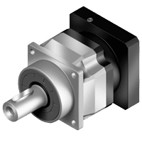
AFX series
In line planetary- High Speed gearbox
- Special design for continuous (S1) or cyclic (S5) duty operation
- Stainless steel housing, aluminum black anodized motor adapter flange
- Stainless steel output shaft with or without key, or with spline (DIN5480)
- Helical gear design
- Nominal torques:
- T2N : 14 Nm - 1.200 Nm
- Ratios
- 1-stage : 3 / 4 / 5 / 6 / 7 / 8 / 9 / 10
- 2-stage : 12 / 15 / 16 / 20 / 25 / 28 / 30 / 32 / 35 / 40 / 45 / 50 / 60 / 70 / 80 / 90 / 100
- Low backlash
- 1-stage : ≤ 1 arcmin / ≤ 3 arcmin / ≤ 5 arcmin
- 2-stage : ≤ 3 arcmin / ≤ 5 arcmin / ≤ 7 arcmin
- High efficiency
- 1-stage : ≥ 97%
- 2-stage : ≥ 94%
- Easy mount
- Low noise
- Compact structure
- Sizes available: AFX042 / AFX060 / AFX060A / AFX075 / AFX075A / AFX100 / AFX100A / AFX140 / AFX140A / AFX180
| Model No. | Stage | RatioA | AFX042E | AFX060 | AFX060A | AFX075 | AFX075A | AFX100 | AFX100A | AFX140 | AFX140A | AFX180 | |
| Nominal Output Torque T2N | Nm | 1 | 3 | 20 | 55 | - | 130 | - | 208 | - | 342 | - | 588 |
| 4 | 19 | 50 | - | 140 | - | 290 | - | 542 | - | 1,050 | |||
| 5 | 22 | 60 | - | 160 | - | 330 | - | 650 | - | 1,200 | |||
| 6 | 20 | 55 | - | 150 | - | 310 | - | 600 | - | 1,100 | |||
| 7 | 19 | 50 | - | 140 | - | 300 | - | 550 | - | 1,100 | |||
| 8 | 17 | 45 | - | 120 | - | 260 | - | 500 | - | 1,000 | |||
| 9 | 14 | 40 | - | 100 | - | 230 | - | 450 | - | 900 | |||
| 10 | 14 | 40 | - | 100 | - | 230 | - | 450 | - | 900 | |||
| 2 | 12 | 19 | - | - | 140 | 140 | 290 | 290 | 542 | 542 | 1,050 | ||
| 15 | 20 | 55 | 55 | 130 | 130 | 208 | 208 | 342 | 342 | 588 | |||
| 16 | 19 | - | - | 140 | 140 | 290 | 290 | 542 | 542 | 1,050 | |||
| 20 | 19 | 50 | 50 | 140 | 140 | 290 | 290 | 542 | 542 | 1,050 | |||
| 25 | 22 | 60 | 60 | 160 | 160 | 330 | 330 | 650 | 650 | 1,200 | |||
| 28 | 19 | - | - | 140 | 140 | 300 | 300 | 550 | 550 | 1,100 | |||
| 30 | 20 | 55 | 55 | 150 | 150 | 310 | 310 | 600 | 600 | 1,100 | |||
| 32 | 17 | - | - | 120 | 120 | 260 | 260 | 500 | 500 | 1,000 | |||
| 35 | 19 | 50 | 50 | 140 | 140 | 300 | 300 | 550 | 550 | 1,100 | |||
| 40 | 17 | 45 | 45 | 120 | 120 | 260 | 260 | 500 | 500 | 1,000 | |||
| 45 | 14 | 40 | 40 | 100 | 100 | 230 | 230 | 450 | 450 | 900 | |||
| 50 | 22 | 60 | 60 | 160 | 160 | 330 | 330 | 650 | 650 | 1,200 | |||
| 60 | 20 | 55 | 55 | 150 | 150 | 310 | 310 | 600 | 600 | 1,100 | |||
| 70 | 19 | 50 | 50 | 140 | 140 | 300 | 300 | 550 | 550 | 1,100 | |||
| 80 | 17 | 45 | 45 | 120 | 120 | 260 | 260 | 500 | 500 | 1,000 | |||
| 90 | 14 | 40 | 40 | 100 | 100 | 230 | 230 | 450 | 450 | 900 | |||
| 100 | 14 | 40 | 40 | 100 | 100 | 230 | 230 | 450 | 450 | 900 | |||
| Emergency Stop Torque T2NotB | Nm | 1,2 | 3~100 | 3 times of Nominal Output Torque T2N | |||||||||
| Nominal Input Speed | Nm | 1,2 | 3~100 | 5,000 | 5,000 | 5,000 | 4,000 | 4,000 | 4,000 | 4,000 | 3,000 | 3,000 | 3,000 |
| Max. Input Speed | NM | 1,2 | 3~100 | 10,000 | 10,000 | 10,000 | 8,000 | 8,000 | 8,000 | 8,000 | 6,000 | 6,000 | 6,000 |
| Micro Backlash P0 | arcmin | 1 | 3~10 | - | - | - | ≤1 | - | ≤1 | - | ≤1 | - | ≤1 |
| 2 | 12~100 | - | - | - | - | - | ≤3 | ≤3 | ≤3 | ≤3 | ≤3 | ||
| Reduced Backlash P1 | arcmin | 1 | 3~10 | ≤3 | ≤3 | - | ≤3 | - | ≤3 | - | ≤3 | - | ≤3 |
| 2 | 12~100 | ≤5 | ≤5 | ≤5 | ≤5 | ≤5 | ≤5 | ≤5 | ≤5 | ≤5 | ≤5 | ||
| Standard Backlash P2 | arcmin | 1 | 3~10 | ≤5 | ≤5 | - | ≤5 | - | ≤5 | - | ≤5 | - | ≤5 |
| 2 | 12~100 | ≤7 | ≤7 | ≤7 | ≤7 | ≤7 | ≤7 | ≤7 | ≤7 | ≤7 | ≤7 | ||
| Torsional Rigidity | Nm/arcmin | 1,2 | 3~100 | 3 | 7 | 7 | 14 | 14 | 25 | 25 | 50 | 50 | 145 |
| Max. Radial Load F2rC | N | 1,2 | 3~100 | 610 | 2,900 | 2,900 | 4,500 | 4,500 | 7,800 | 7,800 | 9,450 | 9,450 | 15,600 |
| Max. Axial Load F2aC | N | 1,2 | 3~100 | 320 | 1,450 | 1,450 | 2,250 | 2,250 | 3,900 | 3,900 | 4,725 | 4,725 | 7,800 |
| Efficiency | % | 1 | 3~10 | ≥97% | |||||||||
| 2 | 12~100 | ≥94% | |||||||||||
| Weight | kg | 1 | 3~10 | 0.6 | 1.7 | - | 3.5 | - | 7.4 | - | 15.8 | - | 32.7 |
| 2 | 12~100 | 0.8 | 2 | 1.5 | 4 | 4.1 | 9 | 11.3 | 19.1 | 22.5 | 37.6 | ||
| Operating Temerature | ºC | 1,2 | 3~100 | -10 C~+90 C | |||||||||
| Lubrication | 1,2 | 12~100 | Synthetic lubrication oils | ||||||||||
| Degree of Gearbox Protection | 1,2 | 3~100 | IP65 | ||||||||||
| Mounting Position | 1,2 | 3~100 | all directions | ||||||||||
| Noise (n1=3000rpm, i=10,No load)D | dB(A) | 1,2 | 3~100 | ≤56 | ≤58 | ≤60 | ≤60 | ≤63 | ≤63 | ≤65 | ≤65 | ≤67 | ≤67 |
A. Ratio ( i=N in / N out )
B. Max. acceleration torque T2B = 60% of T2Not
C. Applied to the output shaft center at 100 rpm
D. These values are measured by gearbox with ratio = 10 (1-stage) or ratio = 100 (2-stage) at 3,000 rpm no loading.
by lower ratio and / or higher RPM, the noise level could be 3 to 5 dB Higher.
E. Continuous operation is not supported.
| Model No. | stages | Ratio1 | AFX042 | AFX060 | AFX060A | AFX075 | AFX075A | AFX100 | AFX100A | AFX140 | AFX140A | AFX180 | |
| Mass Moments of Intertia J1 | kg.cm2 | 1 | 3 | 0.03 | 0.16 | - | 0.61 | - | 3.25 | - | 9.21 | - | 28.98 |
| 4 | 0.03 | 0.14 | - | 0.48 | - | 2.74 | - | 7.54 | - | 23.67 | |||
| 5 | 0.03 | 0.13 | - | 0.47 | - | 2.71 | - | 7.42 | - | 23.29 | |||
| 6 | 0.03 | 0.13 | - | 0.45 | - | 2.65 | - | 7.25 | - | 22.75 | |||
| 7 | 0.03 | 0.13 | - | 0.45 | - | 2.62 | - | 7.14 | - | 22.48 | |||
| 8 | 0.03 | 0.13 | - | 0.44 | - | 2.58 | - | 7.07 | - | 22.59 | |||
| 9 | 0.03 | 0.13 | - | 0.44 | - | 2.57 | - | 7.04 | - | 22.53 | |||
| 10 | 0.03 | 0.13 | - | 0.44 | - | 2.57 | - | 7.03 | - | 22.51 | |||
| 2 | 12 | 0.03 | - | - | 0.16 | 0.61 | 0.61 | 3.25 | 3.25 | 9.21 | 9.21 | ||
| 15 | 0.03 | 0.03 | 0.13 | 0.13 | 0.47 | 0.47 | 2.71 | 2.71 | 7.42 | 7.42 | |||
| 16 | 0.03 | - | - | 0.14 | 0.48 | 0.48 | 2.74 | 2.74 | 7.54 | 7.54 | |||
| 20 | 0.03 | 0.03 | 0.13 | 0.13 | 0.47 | 0.47 | 2.71 | 2.71 | 7.42 | 7.42 | |||
| 25 | 0.03 | 0.03 | 0.13 | 0.13 | 0.47 | 0.47 | 2.71 | 2.71 | 7.42 | 7.42 | |||
| 28 | 0.03 | - | - | 0.14 | 0.48 | 0.48 | 2.74 | 2.74 | 7.54 | 7.54 | |||
| 30 | 0.03 | 0.03 | 0.13 | 0.13 | 0.47 | 0.47 | 2.71 | 2.71 | 7.42 | 7.42 | |||
| 32 | 0.03 | - | - | 0.14 | 0.48 | 0.48 | 2.74 | 2.74 | 7.54 | 7.54 | |||
| 35 | 0.03 | 0.03 | 0.13 | 0.13 | 0.47 | 0.47 | 2.71 | 2.71 | 7.42 | 7.42 | |||
| 40 | 0.03 | 0.03 | 0.13 | 0.13 | 0.47 | 0.47 | 2.71 | 2.71 | 7.42 | 7.42 | |||
| 45 | 0.03 | 0.03 | 0.13 | 0.13 | 0.47 | 0.47 | 2.71 | 2.71 | 7.42 | 7.42 | |||
| 50 | 0.03 | 0.03 | 0.13 | 0.13 | 0.44 | 0.44 | 2.57 | 2.57 | 7.03 | 7.03 | |||
| 60 | 0.03 | 0.03 | 0.13 | 0.13 | 0.44 | 0.44 | 2.57 | 2.57 | 7.03 | 7.03 | |||
| 70 | 0.03 | 0.03 | 0.13 | 0.13 | 0.44 | 0.44 | 2.57 | 2.57 | 7.03 | 7.03 | |||
| 80 | 0.03 | 0.03 | 0.13 | 0.13 | 0.44 | 0.44 | 2.57 | 2.57 | 7.03 | 7.03 | |||
| 90 | 0.03 | 0.03 | 0.13 | 0.13 | 0.44 | 0.44 | 2.57 | 2.57 | 7.03 | 7.03 | |||
| 100 | 0.03 | 0.03 | 0.13 | 0.13 | 0.44 | 0.44 | 2.57 | 2.57 | 7.03 | 7.03 | |||
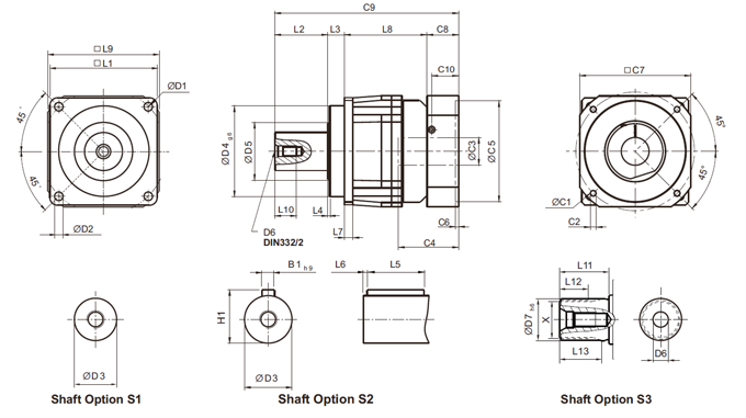
AFX series 1- stage Ratio i=3~10
| AFX042 | AFX060 | AFX075 | AFX100 | AFX140 | AFX180 | |
| D1 | 50 | 68 | 85 | 120 | 165 | 215 |
| D2 | 3.4 | 5.5 | 6.8 | 9 | 11 | 13 |
| D3 | 12j6 | 16h6 | 22h6 | 32h6 | 40h6 | 55h6 |
| D4 g6 | 35 | 60 | 70 | 90 | 130 | 160 |
| D5 | 22 | 21 | 30 | 40 | 75 | 95 |
| D6 | M4 x 0.7P | M5 x 0.8P | M8 x 1.25P | M12 x 1.75P | M16 x 2P | M20 x 2.5P |
| D7 h6 | - | 16 | 22 | 32 | 40 | 55 |
| L1 | 42 | 62 | 76 | 105 | 142 | 180 |
| L2 | 19.5 | 28.5 | 36.5 | 58 | 82 | 82 |
| L3 | 6.5 | 20 | 19.5 | 30 | 30 | 30 |
| L4 | 1 | 1.5 | 1.5 | 2 | 3 | 3 |
| L5 | 14 | 25 | 32 | 40 | 63 | 70 |
| L6 | 2 | 2 | 3 | 5 | 5 | 6 |
| L7 | 4 | 6 | 7 | 10 | 12 | 15 |
| L8 | 31 | 62 | 84 | 103.5 | 132 | 180.5 |
| L9 | 42 | 70 | 90 | 115 | 142 | 180 |
| L10 | 10 | 12.5 | 19 | 28 | 36 | 42 |
| L11 | - | 26 | 26 | 26 | 40 | 41.5 |
| L12 | - | 15 | 15 | 15 | 20 | 21.5 |
| L13 | - | 21 | 22.5 | 23 | 33.5 | 33.5 |
| C11 | 46 | 70 | 100 | 130 | 165 | 215 |
| C21 | M4 x 0.7P | M5 x 0.8P | M6 x 1P | M8 x 1.25P | M10 x 1.5P | M12 x 1.75P |
| C31 | ≤11 / ≤12 2 | ≤14 / ≤16 2 | ≤19 / ≤24 | ≤32 | ≤38 | ≤48 |
| C41 | 25 | 34 | 40 | 50 | 60 | 85 |
| C51 | 30 | 50 | 80 | 110 | 130 | 180 |
| C61 | 3.5 | 8 | 4 | 5 | 6 | 6 |
| C71 | 42 | 60 | 90 | 115 | 142 | 190 |
| C81 | 29.5 | 19 | 17 | 19.5 | 22.5 | 29 |
| C91 | 86.5 | 129.5 | 157 | 211 | 266.5 | 321.5 |
| C101 | 8.75 | 13.5 | 10.75 | 13 | 15 | 20.75 |
| B1 h9 | 4 | 5 | 6 | 10 | 12 | 16 |
| H1 | 13.5 | 18 | 24.5 | 35 | 43 | 59 |
| X DIN5480 | - | W16 x 0.8 x 30 x 18 x 6m |
W22 x 1.25 x 30 x 16 x 6m |
W32 x 1.25 x 30 x 24 x 6m |
W40 x 2 x 30 x 18 x 6m |
W55 x 2 x 30 x 26 x 6m |
1. C1~C10 are motor specific dimensions (metric std shown). Refer to www.apexdyna.com and Design Tool to view your specific motor mounting system.
2. AFX042 ratio 5, 10 offers C3 ≤ 12 option. AFX060 ratio 5, 10 offers C3 ≤ 16 option
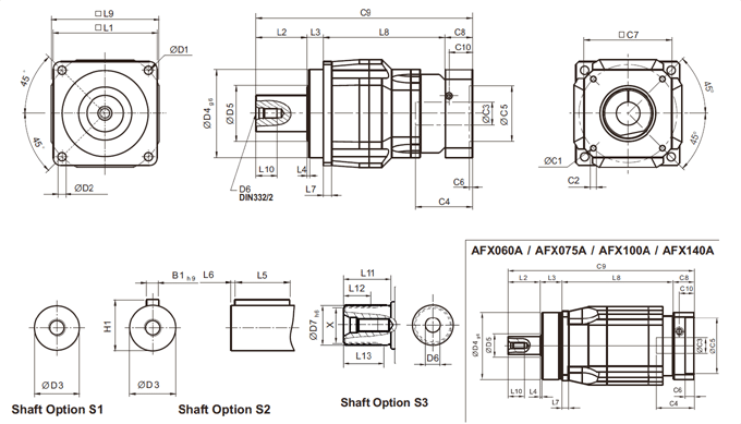
AFX series 2-stage Ratio i=12~100
| Dimension | AFX042 | AFX060 | AFX060A | AFX075 | AFX075A | AFX100 | AFX100A | AFX140 | AFX140A | AFX180 |
| D1 | 50 | 68 | 85 | 120 | 165 | 215 | ||||
| D2 | 3.4 | 5.5 | 6.8 | 9 | 11 | 13 | ||||
| D3 | 12j6 | 16h6 | 22h6 | 32h6 | 40h6 | 55h6 | ||||
| D4 g6 | 35 | 60 | 70 | 90 | 130 | 160 | ||||
| D5 | 22 | 21 | 30 | 40 | 75 | 95 | ||||
| D6 | M4 x 0.7P | M5 x 0.8P | M8 x 1.25P | M12 x 1.75P | M16 x 2P | M20 x 2.5P | ||||
| D7 h6 | - | 16 | 22 | 32 | 40 | 55 | ||||
| L1 | 42 | 62 | 76 | 105 | 142 | 180 | ||||
| L2 | 19.5 | 28.5 | 36.5 | 58 | 82 | 82 | ||||
| L3 | 6.5 | 20 | 19.5 | 30 | 30 | 30 | ||||
| L4 | 1 | 1.5 | 1.5 | 2 | 3 | 3 | ||||
| L5 | 14 | 25 | 32 | 40 | 63 | 70 | ||||
| L6 | 2 | 2 | 3 | 5 | 5 | 6 | ||||
| L7 | 4 | 6 | 7 | 10 | 12 | 15 | ||||
| L8 | 58.5 | 73 | 99 | 117 | 132 | 145 | 164.5 | 188.5 | 203.5 | 236 |
| L9 | 42 | 70 | 90 | 115 | 142 | 180 | ||||
| L10 | 10 | 12.5 | 19 | 28 | 36 | 42 | ||||
| L11 | - | 26 | 26 | 26 | 40 | 41.5 | ||||
| L12 | - | 15 | 15 | 15 | 20 | 21.5 | ||||
| L13 | - | 21 | 22.5 | 23 | 33.5 | 33.5 | ||||
| C11 | 46 | 46 | 70 | 70 | 100 | 100 | 130 | 130 | 165 | 165 |
| C21 | M4 x 0.7P | M4 x 0.7P | M5 x 0.8P | M5 x 0.8P | M6 x 1P | M6 x 1P | M8 x 1.25P | M8 x 1.25P | M10 x 1.5P | M10 x 1.5P |
| C31 | ≤11 / ≤12 2 | ≤11 / ≤12 2 | ≤14 / ≤16 2 | ≤14 / ≤15.875 / ≤16 | ≤19 / ≤24 | ≤19 / ≤24 | ≤32 | ≤32 | ≤38 | ≤38 |
| C41 | 25 | 25 | 34 | 34 | 40 | 40 | 50 | 50 | 60 | 85 |
| C51 | 30 | 30 | 50 | 50 | 80 | 80 | 110 | 110 | 130 | 180 |
| C61 | 3.5 | 3.5 | 8 | 8 | 4 | 4 | 5 | 5 | 6 | 6 |
| C71 | 42 | 42 | 60 | 60 | 90 | 90 | 115 | 115 | 142 | 190 |
| C81 | 29.5 | 29.5 | 19 | 19 | 17 | 17 | 19.5 | 19.5 | 22.5 | 29 |
| C91 | 86.5 | 86.5 | 129.5 | 129.5 | 157 | 157 | 211 | 211 | 266.5 | 321.5 |
| C101 | 8.75 | 8.75 | 13.5 | 13.5 | 10.75 | 10.75 | 13 | 13 | 15 | 20.75 |
| B1 h9 | 4 | 5 | 6 | 10 | 12 | 16 | ||||
| H1 | 13.5 | 18 | 24.5 | 35 | 43 | 59 | ||||
| X DIN5480 | - | W16 x 0.8 x 30 x 18 x 6m |
W22 x 1.25 x 30 x 16 x 6m |
W32 x 1.25 x 30 x 24 x 6m |
W40 x 2 x 30 x 18 x 6m |
W55 x 2 x 30 x 26 x 6m |
||||
3. C1~C10 are motor specific dimensions (metric std shown). Refer to www.apexdyna.com and Design Tool to view your specific motor mounting system.