ADS series
In line planetary- Special design for continuous (S1) or cyclic (S5) duty operation
- Stainles steel housing, aluminum black anodized motor adapter flange
- Stainless steel input and output shaft, flange ISO 9409
- Helical gear technology
- Nominal Torques:
- T2N : 14 Nm - 2000 Nm
- Ratios
- 1-stage : 4 / 5 / 7 / 10
- 2-stage: 16 / 21 / 31 / 61 / 91
- Low Backlash
- 1-stage : ≤ 1 arcmin / ≤ 3 arcmin / ≤ 5 arcmin
- 2-stage : ≤ 3 arcmin / ≤ 5 arcmin / ≤ 7 arcmin
- High Efficiency
- 1-stage : ≥ 97%
- 2-stage : ≥ 94%
- Easy mount
- Low noise
- Compact structure
- Size available: ADS047 / ADS064 / ADS090 / ADS110 / ADS140 / ADS200 / ADS255
|
Model No. |
Stage | Ratio1 | ADS047 | ADS064 | ADS090 | ADS110 | ADS140 | ADS200 | ADS255 | |
| Nominal Output Torque T2N | Nm | 1 | 4 | 19 | 48 | 130 | 270 | 560 | 1,100 | 1,700 |
| 5 | 22 | 60 | 160 | 330 | 650 | 1,200 | 2,000 | |||
| 7 | 19 | 50 | 140 | 300 | 550 | 1,100 | 1,800 | |||
| 10 | 14 | 40 | 100 | 230 | 450 | 900 | 1,500 | |||
| 2 | 16 | 19 | 48 | 130 | 270 | 560 | 1,100 | 1,700 | ||
| 21 | 22 | 60 | 160 | 330 | 650 | 1,200 | 2,000 | |||
| 31 | 19 | 50 | 140 | 300 | 550 | 1,100 | 1,800 | |||
| 61 | 19 | 50 | 140 | 300 | 550 | 1,100 | 1,800 | |||
| 91 | 14 | 40 | 100 | 230 | 450 | 900 | 1,500 | |||
| Emergency Stop Torque T2NOT (2) | Nm | 1,2 | 4~91 | 3 times of nominal output torque T2N | ||||||
| Nominal Input Speed N1N | rpm | 1,2 | 4~91 | 5,000 | 5,000 | 4,000 | 4,000 | 3,000 | 3,000 | 2,000 |
| Max. Input Speed N1B | rpm | 1,2 | 4~91 | 10,000 | 10,000 | 8,000 | 7,500 | 4,500 | 4,500 | 3,800 |
| Micro Backlash P0 | arcmin | 1 | 4~10 | - | - | ≤ 1 | ≤ 1 | ≤ 1 | ≤ 1 | ≤ 1 |
| 2 | 16~91 | - | - | - | ≤ 3 | ≤ 3 | ≤ 3 | ≤ 3 | ||
| Reduced Backlash P1 | arcmin | 1 | 4~10 | ≤ 3 | ≤ 3 | ≤ 3 | ≤ 3 | ≤ 3 | ≤ 3 | ≤ 3 |
| 2 | 16~91 | ≤ 5 | ≤ 5 | ≤ 5 | ≤ 5 | ≤ 5 | ≤ 5 | ≤ 5 | ||
| Standard Backlash P2 | arcmin | 1 | 4~10 | ≤ 5 | ≤ 5 | ≤ 5 | ≤ 5 | ≤ 5 | ≤ 5 | ≤ 5 |
| 2 | 16~91 | ≤ 7 | ≤ 7 | ≤ 7 | ≤ 7 | ≤ 7 | ≤ 7 | ≤ 7 | ||
| Torsional Rigidity | Nm/ arcmin |
1,2 | 4~91 | 3 | 7 | 14 | 25 | 50 | 145 | 225 |
| Max. Tilting moment M2k | Nm | 1,2 | 4~91 | 55 | 75 | 190 | 300 | 1,300 | 2,930 | 5,500 |
| Max. axial load | N | 1,2 | 4~91 | 990 | 1,050 | 2,850 | 2,990 | 10,590 | 16,660 | 29,430 |
| Input Max. Radial Load F1rB(3) | N | 1 | 4~10 | 165 | 395 | 1,300 | 1,525 | 2,800 | 4,500 | 12,500 |
| 2 | 16~91 | 165 | 165 | 395 | 1,300 | 1,525 | 2,800 | 4,500 | ||
| Input Max. Axial Load F1aB(3) | N | 1 | 4~10 | 580 | 1,000 | 1,100 | 980 | 2,700 | 4,700 | 8,000 |
| 2 | 16~91 | 580 | 580 | 1,000 | 1,100 | 980 | 2,700 | 4,700 | ||
| Efficiency | % | 1 | 4~10 | ≥ 97 % | ||||||
| 2 | 16~91 | ≥ 94 % | ||||||||
| Weight | kg | 1 | 4~10 | 0.8 | 1.4 | 3.4 | 6.7 | 13.5 | 35.0 | 63.8 |
| 2 | 16~91 | 1.1 | 1.6 | 4.0 | 7.3 | 16.6 | 36.4 | 74.7 | ||
| Operating Temperature | ºC | 1,2 | 4~91 | -10ºC ~+ 90ºC | ||||||
| Lubrication | 1,2 | 4~91 | synthetic gear grease | |||||||
| Degree of Gearbox Protection | 1,2 | 4~91 | IP65 | |||||||
| Mounting Position | 1,2 | 4~91 | all directions | |||||||
| Noise Level (4) | dB(A) | 1,2 | 4~91 | ≤ 56 | ≤ 58 | ≤ 60 | ≤ 63 | ≤ 65 | ≤ 67 | ≤ 70 |
- Ratio ( i = N in / N out )
- Applied to the output flange center at 100 rpm
- Maximum acceleration torque T2B = 60% van T2NOT
- These values are measured by gearbox with ratio 10 (1-stage) or ratio 100 (2-stage) at 3,000 rpm no loading.
By lower ratio and/or higher RPM, the noise level could be 3 to 5 dB higher.
Maximum tilting moment:
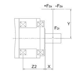
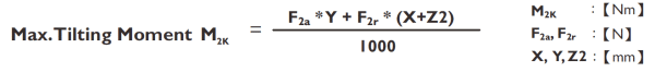
| Size | ADS047 | ADS064 | ADS090 | ADS110 | ADS140 | ADS200 | AB255 | |
| Z2 (mm) | 37.9 | 46.2 | 63.1 | 75.5 | 92.2 | 119.2 | 148.8 | |
Applied to the output flange center at 100 rpm
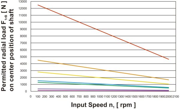
Maximum radial and axial loads:
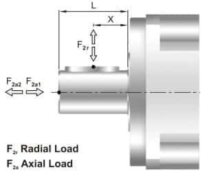
The maximum radial and axial loads on the input shaft of the gearbox depends on the design of the gearbox supporting bearings.
Apex Dynamics uses the extension straddle oversized ball bearing design. This can take heavy load from both axles
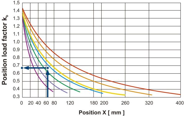
Permitted radial load F2r on center of output shaft X = ½ x L for various output speeds.
If radial force F2r is not exerted on the center of the ouput shaft X < ½ x L or X > ½ x L, the permitted radial and axial loads can be calculated by the position load factor Kb on the above diagram.
|
Model No. |
Stage | Ratio1 | ADS047 | ADS064 | ADS090 | ADS110 | ADS140 | ADS200 | ADS255 | |
| Mass Moment of inertia J1 | kg*cm2 | 1 | ||||||||
| 4 | 0.06 | 0.21 | 0.87 | 3.65 | 10.27 | 43.05 | 102.68 | |||
| 5 | 0.06 | 0.21 | 0.83 | 3.53 | 10.17 | 41.76 | 99.12 | |||
| 7 | 0.06 | 0.21 | 0.82 | 3.47 | 9.99 | 41.15 | 97.41 | |||
| 10 | 0.06 | 0.21 | 0.81 | 3.45 | 9.93 | 40.97 | 97.03 | |||
| 2 | ||||||||||
| 16 | 0.06 | 0.06 | 0.21 | 0.83 | 3.53 | 10.17 | 41.76 | |||
| 21 | 0.06 | 0.06 | 0.21 | 0.83 | 3.53 | 10.17 | 41.76 | |||
| 31 | 0.06 | 0.06 | 0.21 | 0.83 | 3.53 | 10.17 | 41.76 | |||
| 61 | 0.06 | 0.06 | 0.21 | 0.81 | 3.45 | 9.93 | 40.97 | |||
| 91 | 0.06 | 0.06 | 0.21 | 0.81 | 3.45 | 9.93 | 40.97 | |||
ADS series 1-stage, ratio i= 4~10
| ADS047 | ADS064 | ADS090 | ADS110 | ADS140 | ADS200 | ADS255 | |
| D1 H7 | 12 | 20 | 31.5 | 40 | 50 | 80 | 100 |
| D2 | 20 | 31.5 | 50 | 63 | 80 | 125 | 140 |
| D3 h7 | 28 | 40 | 63 | 80 | 100 | 160 | 180 |
| D4 h7 | 47 | 64 | 90 | 110 | 140 | 200 | 255 |
| D5 | 67 | 79 | 109 | 135 | 168 | 233 | 280 |
| D6 | 4 X M3 X 0.5P | 7 X M5 X 0.8P | 7 X M6 X 1P | 11 X M6 X 1P | 11 X M8 X 1.25P | 11 X M10 X 1.5P | 12 X M16 X 2P |
| D7 | 72 | 86 | 118 | 145 | 179 | 247 | 300 |
| D8 H7 | 3 | 5 | 6 | 6 | 8 | 10 | 12 |
| D9 | 43 | 55 | 78 | 100 | 125 | 175 | 210 |
| D10 | 8 X 3.4 | 8 X 4.5 | 8 X 5.5 | 8 X 5.5 | 12 X 6.6 | 12 X 9 | 16 X 13.5 |
| D11 h7 | 60 | 70 | 95 | 120 | 152 | 212 | 255 |
| D12 | 31 | 22 | 22 | 30 | 40 | 75 | 95 |
| D13 | 37 | 50 | 62 | 82 | 108 | 145 | 172 |
| D14 | M4 x 0.7P | M4 x 0.7P | M5 x 0.8P | M8 x 1.25P | M12 x 1.75P | M16 x 2P | M20 x 2.5P |
| D15 | M3 x 0.5P | M3 x 0.5P | M4 x 0.7P | M5 x 0.8P | M6 x 1P | M8 x 1.25P | M8 x 1.25P |
| D16 | 51.5 | 61.5 | 84 | 107 | 137 | 193 | 235 |
| D1 7k6 | 11 | 14 | 16 | 22 | 32 | 40 | 55 |
| D18 | 46.2 | 63.2 | 89.2 | 109.2 | 139.2 | 199.2 | 254.2 |
| L1 | 4 | 8 | 12 | 12 | 12 | 16 | 20 |
| L2 | 6.5 | 8 | 13.5 | 13.5 | 17 | 22.5 | 30.5 |
| L3 | 3 | 3 | 6 | 6 | 6 | 8 | 12 |
| L4 | 19.5 | 19.5 | 30 | 29 | 38 | 50 | 66 |
| L5 | 7 | 7 | 10 | 10 | 14.6 | 15 | 20 |
| L6 | 4 | 4 | 7 | 8 | 10 | 12 | 18 |
| L7 | 5 | 7.7 | 8 | 10 | 12 | 15 | 20 |
| L8 | 32.5 | 43.5 | 47 | 62 | 72 | 89.5 | 112 |
| L9 | 4 | 6 | 7 | 7 | 7 | 10 | 10 |
| L10 | 0.5 | 0.5 | 1 | 1 | 1 | 1 | 1 |
| L11 | 89.5 | 110.5 | 138.5 | 170 | 218 | 296 | 372.5 |
| L12 | 18 | 22 | 28 | 36 | 58 | 82 | 115 |
| L13 | 2.5 | 2.5 | 3.5 | 3.5 | 3.5 | 4.5 | 4.5 |
| L14 | 10 | 10 | 12.5 | 19 | 28 | 36 | 42 |
| L15 | 1.5 | 1.5 | 1.5 | 1.5 | 1.5 | 1.5 | 1.5 |
| L16 | 5.5 | 5.5 | 7 | 9 | 11 | 14 | 14 |
| L17 | 2 | 2 | 3 | 3 | 6 | 6 | 7 |
| L18 | 14 | 18 | 22 | 28 | 45 | 70 | 90 |
| B1 h9 | 4 | 5 | 5 | 6 | 10 | 12 | 16 |
| H1 | 12.5 | 16 | 18 | 24.5 | 35 | 43 | 59 |
| OD | 56 X 2 | 66 X 2 | 90 X 3 | 110 X 3 | 145 X 3 | 200 X 5 | 238 X 5 |
| V | 4 | 4 | 4 | 4 | 6 | 6 | 6 |
| Z | 45 | 45 | 45 | 45 | 30 | 30 | 30 |
ADS series 2-stage, ratio i= 16~91
| ADS047 | ADS064 | ADS090 | ADS110 | ADS140 | ADS200 | ADS255 | |
| D1 H7 | 12 | 20 | 31.5 | 40 | 50 | 80 | 100 |
| D2 | 20 | 31.5 | 50 | 63 | 80 | 125 | 140 |
| D3 h7 | 28 | 40 | 63 | 80 | 100 | 160 | 180 |
| D4 h7 | 47 | 64 | 90 | 110 | 140 | 200 | 255 |
| D5 | 67 | 79 | 109 | 135 | 168 | 233 | 280 |
| D6 | 4 X M3 X 0.5P | 7 X M5 X 0.8P | 7 X M6 X 1P | 11 X M6 X 1P | 11 X M8 X 1.25P | 11 X M10 X 1.5P | 12 X M16 X 2P |
| D7 | 72 | 86 | 118 | 145 | 179 | 247 | 300 |
| D8 H7 | 3 | 5 | 6 | 6 | 8 | 10 | 12 |
| D9 | 43 | 48 | 68 | 86 | 110 | 132 | 182 |
| D10 | 8 X 3.4 | 8 X 4.5 | 8 X 5.5 | 8 X 5.5 | 12 X 6.6 | 12 X 9 | 16 X 13.5 |
| D11 h7 | 60 | 70 | 95 | 120 | 152 | 212 | 255 |
| D12 | 22 | 22 | 22 | 22 | 30 | 40 | 75 |
| D13 | 37 | 37 | 50 | 62 | 82 | 108 | 145 |
| D14 | M4 x 0.7P | M4 x 0.7P | M4 x 0.7P | M5 x 0.8P | M8 x 1.25P | M12 x 1.75P | M16 x 2P |
| D15 | M3 x 0.5P | M3 x 0.5P | M4 x 0.7P | M5 x 0.8P | M6 x 1P | M8 x 1.25P | M10 x 1.5P |
| D16 | 51.5 | 61.5 | 84 | 107 | 137 | 193 | 235 |
| D17 k6 | 11 | 11 | 14 | 16 | 22 | 32 | 40 |
| D18 | 46.2 | 63.2 | 89.2 | 109.2 | 139.2 | 199.12 | 254.2 |
| L1 | 4 | 8 | 12 | 12 | 12 | 16 | 20 |
| L2 | 6.5 | 8 | 13.5 | 13.5 | 17 | 22.5 | 30.5 |
| L3 | 3 | 3 | 6 | 6 | 6 | 8 | 12 |
| L4 | 19.5 | 19.5 | 30 | 29 | 38 | 50 | 66 |
| L5 | 7 | 7 | 10 | 10 | 14.6 | 15 | 20 |
| L6 | 4 | 4 | 7 | 8 | 10 | 12 | 18 |
| L7 | 5 | 7.7 | 8 | 10 | 12 | 15 | 20 |
| L8 | 62.5 | 63.5 | 67 | 82 | 122 | 79.5 | 177 |
| L9 | 4 | 6 | 7 | 7 | 7 | 10 | 10 |
| L10 | 0.5 | 0.5 | 1 | 1 | 1 | 1 | 1 |
| L11 | 119.5 | 125.5 | 158.5 | 188 | 253.5 | 314.5 | 419.5 |
| L12 | 18 | 18 | 22 | 28 | 36 | 58 | 82 |
| L13 | 2.5 | 2.5 | 2.5 | 3.5 | 3.5 | 3.5 | 4.5 |
| L14 | 10 | 10 | 10 | 12.5 | 19 | 28 | 36 |
| L15 | 1.5 | 1.5 | 1.5 | 1.5 | 1.5 | 1.5 | 1.5 |
| L16 | 5.5 | 5.5 | 7 | 9 | 11 | 14 | 18 |
| L17 | 2 | 2 | 2 | 3 | 3 | 6 | 6 |
| L18 | 14 | 14 | 18 | 22 | 28 | 45 | 70 |
| B1 h9 | 4 | 4 | 5 | 5 | 6 | 10 | 12 |
| H1 | 12.5 | 12.5 | 16 | 18 | 24.5 | 35 | 43 |
| OD | 56 X 2 | 66 X 2 | 90 X 3 | 110 X 3 | 145 X 3 | 200 X 5 | 238 X 5 |
| V | 4 | 4 | 4 | 4 | 6 | 6 | 6 |
| Z | 45 | 45 | 45 | 45 | 30 | 30 | 30 |
Dimensions Output Flange( ISO 9409 )
ADS series
| Dimension | ADS047 | ADS064 | ADS090 | ADS110 | ADS140 | ADS200 | ADS255 |
| D1 H7 | 12 | 20 | 31.5 | 40 | 50 | 80 | 100 |
| D2 | 20 | 31.5 | 50 | 63 | 80 | 125 | 140 |
| D3 h7 | 28 | 40 | 63 | 80 | 100 | 160 | 180 |
| D4 h7 | 47 | 64 | 90 | 110 | 140 | 200 | 255 |
| D5 | 67 | 79 | 109 | 135 | 168 | 233 | 280 |
| D6 | M3 x 0.5P | M5 x 0.8P | M6 x 1P | M6 x 1P | M8 x 1.25P | M10 x 1.5P | M16 x 2P |
| D8 H7 | 3 | 5 | 6 | 6 | 8 | 10 | 12 |
| D10 | 3.4 | 4.5 | 5.5 | 5.5 | 6.6 | 9 | 13.5 |