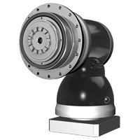
Hypoid
APCK series
- Heavy duty right-angled hypoid gearbox
- Output flange Curvic Plate
- Ratio 16 to 5500
- Torque 190 Nm – 18,715Nm
- Heavy Duty right-angle hypoïd gearbox
- Black coated steel housing and output flange, aluminum motor adapter
- Steel output shaft, with Curvic Plate flange
- Helical gear technology
- Nominal Torques:
- T2N : 190 Nm - 18,715 Nm
- Ratios
- 2-stage : 16 / 20 / 22 / 27.5 / 28 / 38.5 / 40 / 55
- 3-stage : 64 / 88 / 100 / 110 / 137.5 / 140 / 154 / 160 / 200 / 220 / 280 / 385
- 4-stage : 400 / 440 / 500 / 550 / 700 / 770 / 1000 / 1078 / 1400 / 1540 / 1600 / 2000 / 2695 / 2800 / 3850 / 4000 / 5500
- Low Backlash
- 2-stage : ≤ 2 arcmin
- 3-stage : ≤ 2 arcmin
- 4-stage: ≤ 2 arcmin
- High Efficiency
- 2-stage : ≥ 94%
- 3-stage : ≥ 92%
- 4-stage : ≥ 90%
- Easy mount
- Low noise
- Compact structure
- Sizes available: APCK090 / APCK110 / APCK140 / APCK200 / APCK255 / APCK285 / APCK355 / APCK450
| Model No. | Stage | Ratio(¹) | APCK090 | APCK110 | APCK140 | APCK200 | APCK255 | APCK285 | APCK355 | APCK450 | |
| Nominal Output Torque T2N | Nm | 2 | 16 | 255 | 528 | 848 | 1,800 | 2,015 | 3,935 | - | - |
| 20 | 255 | 528 | 848 | 1,800 | 2,015 | 3,935 | - | - | |||
| 22 | 245 | 465 | 780 | 1,740 | 2,685 | 4,815 | 8,670 | - | |||
| 27.5 | 245 | 465 | 785 | 1,750 | 2,700 | 4,840 | 8,720 | - | |||
| 28 | 240 | 480 | 848 | 1,800 | 1,872 | 3,600 | - | - | |||
| 38.5 | 245 | 470 | 795 | 1,770 | 2,574 | 4,885 | 8,795 | - | |||
| 40 | 192 | 408 | 816 | 1,725 | 1,728 | 2,880 | - | - | |||
| 55 | 250 | 475 | 805 | 1,785 | 2,376 | 3,790 | 7,260 | - | |||
| 3 | 64 | - | 565 | 845 | 2,080 | 3,220 | 5,815 | - | - | ||
| 88 | - | 480 | 815 | 1,800 | 2,185 | 4,970 | 8,910 | 17,020 | |||
| 100 | - | 565 | 845 | 2,105 | 3,260 | 5,815 | - | - | |||
| 110 | - | 480 | 820 | 1,810 | 2,800 | 4,990 | 8,950 | 17,105 | |||
| 137.5 | - | 480 | 825 | 1,820 | 2,815 | 5,020 | 8,995 | 17,190 | |||
| 140 | - | 565 | 840 | 2,125 | 3,285 | 5,815 | - | - | |||
| 154 | - | 485 | 825 | 1,825 | 2,820 | 5,035 | 8,580 | 16,500 | |||
| 160 | - | 565 | 845 | 2,130 | 3,295 | 5,760 | - | - | |||
| 200 | - | 565 | 845 | 2,145 | 3,315 | 5,815 | - | - | |||
| 220 | - | 490 | 835 | 1,840 | 2,850 | 5,070 | 7,920 | 13,200 | |||
| 280 | - | 540 | 845 | 2,160 | 3,345 | 5,815 | - | - | |||
| 385 | - | 495 | 850 | 1,845 | 2,890 | 5,130 | 9,195 | 17,565 | |||
| 4 | 400 | - | 565 | 845 | 2,155 | 3,320 | 5,815 | - | - | ||
| 440 | - | 450 | 835 | 1,840 | 2,840 | 5,110 | 9,070 | 17,335 | |||
| 500 | - | 565 | 845 | 2,165 | 3,340 | 6,195 | - | - | |||
| 550 | - | 490 | 845 | 1,860 | 2,870 | 5,150 | 9,155 | 17,485 | |||
| 700 | - | 590 | 995 | 2,185 | 3,370 | 5,815 | - | - | |||
| 770 | - | 495 | 850 | 1,870 | 2,895 | 5,180 | 9,225 | 17,600 | |||
| 1,000 | - | 565 | 810 | 2,205 | 3,400 | 5,815 | - | - | |||
| 1,078 | - | 500 | 860 | 1,890 | 2,920 | 5,220 | 8,580 | 16,500 | |||
| 1,400 | - | 540 | 845 | 2,220 | 3,430 | 5,760 | - | - | |||
| 1,540 | - | 500 | 870 | 1,910 | 2,945 | 5,815 | 7,920 | 13,200 | |||
| 1,600 | - | 565 | 845 | 2,225 | 3,435 | 5,275 | - | - | |||
| 2,000 | - | 565 | 810 | 2,240 | 3,455 | 5,815 | - | - | |||
| 2,695 | - | 510 | 880 | 1,935 | 2,980 | 5,275 | 9,440 | 18,015 | |||
| 2,800 | - | 540 | 845 | 2,225 | 3,480 | 5,815 | - | - | |||
| 3,850 | - | 540 | 980 | 1,610 | 2,995 | 5,365 | 9,585 | 18,245 | |||
| 4,000 | - | 225 | 650 | 1,840 | 3,515 | 5,815 | - | - | |||
| 5,500 | - | 315 | 895 | 1,980 | 3,110 | 5,515 | 9,825 | 18,715 | |||
| Emergency Stop Torque T2Not | Nm | 2,3,4 | 16~5,500 | 2 times T2N | |||||||
| Max. Acceleration Torque T2b | Nm | 2,3,4 | 16~5,500 | 1.5 times T2N | |||||||
| No Load Running Torque(2) | NM | 2 | 16~55 | 1.3 | 2 | 3.1 | 6 | 13 | 16 | 20 | - |
| 3 | 64~385 | - | 1.4 | 2.4 | 4.6 | 7 | 8.5 | 10.5 | 13 | ||
| 4 | 400~5,500 | - | 0.2 | 0.3 | 0.6 | 0.9 | 1.2 | 1.8 | 2.5 | ||
| Backlash(3) | arcmin | 2,3,4 | 16~5,500 | ≤ 2 | |||||||
| Torsional Rigidity | Nm/arcmin | 2 | 16~55 | 27 | 56 | 112 | 389 | 642 | 1,275 | 2,500 | - |
| 3 | 64~385 | - | 56 | 112 | 389 | 642 | 1,275 | 2,500 | 5,100 | ||
| 4 | 400~5,500 | - | 45 | 85 | 310 | 535 | 1,050 | 1,700 | 2,700 | ||
| Nominal Input Speed n1N | rpm | 2 | 16~55 | 3,000 | 2,800 | 2,700 | 2,200 | 2,100 | 2,000 | 1,600 | - |
| 3 | 64~385 | 3,000 | 3,000 | 2,800 | 2,700 | 2,200 | 2,100 | 2,100 | 2,000 | ||
| 4 | 400~5,500 | 5,500 | 5,500 | 4,600 | 4,600 | 4,000 | 3,700 | 3,700 | 3,400 | ||
| Max. Input Speed | rpm | 2 | 16~55 | 6,000 | 6,000 | 4,500 | 4,500 | 4,000 | 3,000 | 2,500 | - |
| 3 | 64~385 | 6,000 | 6,000 | 6,000 | 4,500 | 4,500 | 4,000 | 4,000 | 3,000 | ||
| 4 | 400~5,500 | 7,000 | 7,000 | 7,000 | 7,000 | 6,000 | 5,500 | 5,500 | 5,000 | ||
| Max. Axial Load F2a(4) | N | 2,3,4 | 16~5,500 | 2,220 | 4,070 | 8,530 | 17,000 | 26,900 | 39,200 | 101,500 | 143,700 |
| Max. Tilting Moment M2k(4) | Nm | 2,3,4 | 16~5,500 | 280 | 480 | 1,310 | 3,530 | 5,920 | 9,230 | 29,100 | 63,300 |
| Operating Temp. | °C | 2,3,4 | 16~5,500 | -10º C < + 90º C | |||||||
| Degree of Gearbox Protection | 2,3,4 | 16~5,500 | IP65 | ||||||||
| Lubrication | 2,3,4 | 16~5,500 | Synthetic lubrication grease | ||||||||
| Mounting Position | 2,3,4 | 16~5,500 | All directions | ||||||||
| Running Noise (2) | dB(A) | 2,3,4 | 16~5,500 | ≤68 | ≤68 | ≤68 | ≤70 | ≤70 | ≤72 | ≤74 | ≤76 |
| Efficiency | % | 2 | 16~55 | ≥94% | |||||||
| 3 | 64~385 | ≥92% | |||||||||
| 4 | 400~5,500 | ≥90% | |||||||||
- Ratio ( i = N in / N out )
- These values are measured by gearbox with ratio 55 (2-stage), ratio 385 (3-stage) or 5500 (4-stage) at 3,000 rpm no loading.
- Backlash is measured at 2% of Nominal output torque T2N.
- Applied to the output flange center at 100 rpm.
- Continuous operation is not recommended.
Maximum tilting moment:


| Size | APCK090 | APCK110 | APCK140 | APCK200 | APCK255 | APCK285 | APCK355 | APCK450 | |
| Z2 (mm) | 84.5 | 106.2 | 90 | 122.8 | 133.2 | 175.5 | 220.6 | 275.3 | |
Applied to the output flange center at 100 rpm.
| Model No. | APCK090 | APCK110 | APCK140 | APCK200 | APCK255 | APCK285 | APCK355 | APCK450 | ||||||||||||||
| Ø(1) | Stage | 2 | 2 | 3 | 4 | 2 | 3 | 4 | 2 | 3 | 4 | 2 | 3 | 4 | 2 | 3 | 4 | 2 | 3 | 4 | 3 | 4 |
| 8 | kg.cm2 | - | - | - | 0.17 | - | - | - | - | - | - | - | - | - | - | - | - | - | - | - | - | - |
| 11 | - | - | - | 0.17 | - | - | - | - | - | - | - | - | - | - | - | - | - | - | - | - | - | |
| 14 | 0.37 | - | 0.37 | - | - | - | 0.42 | - | - | - | - | - | - | - | - | - | - | - | - | - | - | |
| 19 | 0.60 | 1.61 | 0.60 | - | - | 1.61 | 0.66 | - | - | 1.83 | - | - | - | - | - | - | - | - | - | - | - | |
| 24 | - | 3.90 | - | - | 4.01 | 3.90 | 3.94 | - | 4.01 | 4.11 | - | - | 4.61 | - | - | - | - | - | - | - | - | |
| 28 | - | - | - | - | 5.53 | 5.15 | - | - | 5.53 | - | - | 5.61 | 8.14 | - | - | - | - | - | - | - | - | |
| 32 | - | - | - | - | 7.57 | - | - | 8.11 | 7.578 | - | - | 8.11 | 8.17 | - | - | - | - | - | - | - | - | |
| 35 | - | - | - | - | 14.95 | - | - | 15.32 | 14.95 | - | 15.32 | 15.32 | 15.54 | - | 15.32 | 15.54 | - | - | 15.54 | - | 17.76 | |
| 38 | - | - | - | - | 17.58 | - | - | 17.72 | 17.58 | - | 17.72 | 17.72 | 18.19 | 18.52 | 17.72 | 18.19 | - | 17.72 | 18.19 | 18.52 | 20.17 | |
| 42 | - | - | - | - | - | - | - | 22.95 | - | - | 22.95 | - | - | 23.74 | 22.95 | 23.20 | 25.5 | 22.95 | 23.20 | 23.74 | 25.40 | |
| 48 | - | - | - | - | - | - | - | 52.74 | - | - | 52.74 | - | - | 53.49 | 52.74 | 52.42 | 55.14 | 52.74 | 54.42 | 53.49 | 55.18 | |
| 55 | - | - | - | - | - | - | - | - | - | - | - | - | - | 87.34 | - | - | 89.59 | - | - | - | - | |
(1) Ø = Input shaft diameter.
APCK series 2-stage, ratio i=16~55
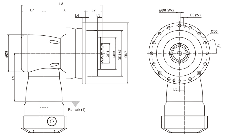
| APCK090 | APCK110 | APCK140 | APCK220 | APCK255 | APCK285 | APCK355 | |
| D1 | 36 | 46 | 60 | 80 | 90 | 120 | 120 |
| D3 | 63 | 80 | 100 | 160 | 180 | 200 | 250 |
| D4 h7 | 90 | 110 | 140 | 200 | 255 | 285 | 355 |
| D5 | 109 | 135 | 168 | 233 | 280 | 310 | 385 |
| D6 | - | - | - | - | M12 | M12 | M16 |
| D7 | 120 | 147 | 180 | 249.5 | 302 | 332 | 415 |
| D8 | 5.5 | 5.5 | 6.6 | 9 | 13.5 | 13.5 | 17.5 |
| D9 | 94 | 116 | 163 | 210 | 210 | 255 | 300 |
| L2 | 32.5 | 31.5 | 40.5 | 52.5 | 68.5 | 77.5 | 82.5 |
| L3 | 9.5 | 9.5 | 10 | 11 | 16 | 19 | 22.5 |
| L4 | 7 | 8 | 100 | 12 | 18 | 20 | 45 |
| L5 | 13 | 17 | 25 | 31 | 31 | 36 | 43 |
| L6 | 90.5 | 114 | 147.5 | 175 | 191.5 | 249.5 | 290 |
| L7 | 53 | 68.3 | 89 | 115 | 115 | 131 | 165 |
| L8 | 176 | 213.8 | 277 | 342.5 | 375 | 458 | 537.5 |
| L9 | 114.5 | 129 | 173.5 | 228 | 228 | 265.5 | 294.5 |
| U in degree | 22.5 | 22.5 | 15 | 15 | 11.25 | 11.25 | 15 |
| W | 16 | 16 | 24 | 24 | 32 | 32 | 24 |
(1) Dimensions are related to motor interface. Please contact APEX for details.
APCK series 3-stage, ratio i=64~385
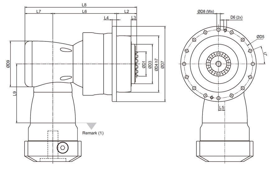
| APCK110 | APCK140 | APCK200 | APCK255 | APCK285 | APCK355 | APCK450 | |
| D1 | 46 | 60 | 80 | 90 | 120 | 120 | 132 |
| D3 | 80 | 100 | 160 | 180 | 200 | 250 | 315 |
| D4 h7 | 110 | 140 | 200 | 255 | 285 | 355 | 450 |
| D5 | 135 | 168 | 233 | 280 | 310 | 385 | 490 |
| D6 | - | - | - | M12 | M12 | M16 | M16 |
| D7 | 147 | 180 | 249.5 | 302 | 332 | 415 | 530 |
| D8 | 5.5 | 6.6 | 9 | 13.5 | 13.5 | 17.5 | 22 |
| D9 | 94 | 116 | 163 | 210 | 210 | 210 | 255 |
| L2 | 31.5 | 40.5 | 52.5 | 68.5 | 77.5 | 82.5 | 87.5 |
| L3 | 9.5 | 10 | 11 | 16 | 19 | 22.5 | 22.5 |
| L4 | 8 | 10 | 12 | 18 | 20 | 45 | 60 |
| L5 | 13 | 17 | 25 | 31 | 31 | 31 | 36 |
| L6 | 132 | 164 | 216.5 | 254.5 | 30 | 332 | 447.5 |
| L7 | 53 | 68.3 | 89 | 115 | 115 | 115 | 131 |
| L8 | 216.5 | 272.8 | 358 | 428 | 492.5 | 529.5 | 666 |
| L9 | 114.5 | 129 | 173.5 | 228 | 228 | 228 | 265.5 |
| U in degree | 22.5 | 15 | 15 | 11.25 | 11.25 | 15 | 15 |
| W | 16 | 24 | 24 | 32 | 32 | 24 | 24 |
(1) Dimensions are related to motor interface. Please contact APEX for details.
APCK series 4-stage, ratio i=400~5,500
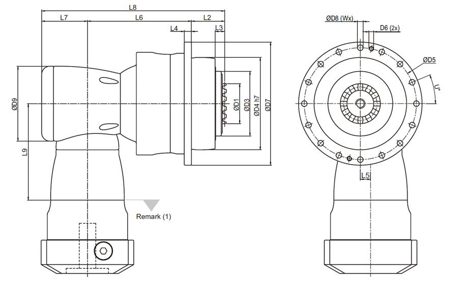
| APCK110 | APCK140 | APCK200 | APCK255 | APCK285 | APCK355 | APCK450 | |
| D1 | 46 | 60 | 80 | 90 | 120 | 120 | 132 |
| D3 | 80 | 100 | 160 | 180 | 200 | 250 | 315 |
| D4 h7 | 110 | 140 | 200 | 255 | 285 | 355 | 450 |
| D5 | 135 | 168 | 233 | 280 | 310 | 385 | 490 |
| D6 | - | - | - | M12 | M12 | M16 | M16 |
| D7 | 147 | 180 | 249.5 | 302 | 332 | 415 | 530 |
| D8 | 5.5 | 6.6 | 9 | 13.5 | 13.5 | 17.5 | 22 |
| D9 | 94 | 116 | 163 | 210 | 210 | 210 | 255 |
| L2 | 31.5 | 40.5 | 52.5 | 68.5 | 77.5 | 82.5 | 87.5 |
| L3 | 9.5 | 10 | 11 | 16 | 19 | 22.5 | 22.5 |
| L4 | 8 | 10 | 12 | 18 | 20 | 45 | 60 |
| L5 | 13 | 17 | 25 | 31 | 31 | 31 | 36 |
| L6 | 132 | 164 | 216.5 | 254.5 | 300 | 332 | 447.5 |
| L7 | 53 | 68.3 | 89 | 115 | 115 | 115 | 131 |
| L8 | 216.5 | 272.8 | 358 | 438 | 492.5 | 529.5 | 666 |
| L9 | 114.5 | 129 | 173.5 | 228 | 228 | 228 | 265.5 |
| U in degree | 22.5 | 15 | 15 | 11.25 | 11.25 | 15 | 15 |
| W | 16 | 24 | 24 | 32 | 32 | 24 | 24 |
(1) Dimensions are related to motor interface. Please contact APEX for details.
Need help with your application? Our specialists are happy to use their years of experience to assist you in selecting the right products.