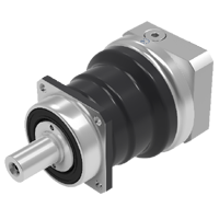
In line planetary
MF series
- High torque gearbox
- Output shaft with or without key, with spline (DIN 5480) or hollow shaft
- Ratio 3 to 100
- High torque gearbox
- Special design for continuous (S1) or cyclic (S5) duty operation
- Steel housing/aluminum, aluminum black anodized motor adapter flange
- Steel output shaft with or without key, with spline (DIN5480) or hollow shaft
- Helical gear design
- Nominal torques:
- T2N : 24 Nm - 4.290 Nm
- Ratios
- 1-stage : 3 / 4 / 5 / 7 / 10
- 2-stage : 16 / 20 / 25 / 28 / 35 / 40 / 50 / 70 / 100
- Low backlash
- 1-stage : ≤ 3 arcmin
- 2-stage : ≤ 4 arcmin
- High efficiency
- 1-stage : ≥ 97%
- 2-stage : ≥ 94%
- Easy mount
- Low noise
- Compact structure
- Sizes available: MF060 / MF075 / MF100 / MF140 / MF180 / MF210 / MF240
| Model No. | Stage | Ratio¹ | MF060 | MF075 | MF100 | MF140 | MF180 | MF210 | MF240 | |
| Nominal Output Torque T2N | Nm | 1 | 3 | 30 | 105 | 200 | 395 | 825 | 1,385 | 3,110 |
| 4 | 100 | 205 | 380 | 765 | 1,415 | 2,190 | 4,035 | |||
| 5 | 85 | 185 | 325 | 660 | 1,225 | 1,905 | 3,505 | |||
| 7 | 60 | 135 | 260 | 515 | 980 | 1,530 | 2,530 | |||
| 10 | 24 | 55 | 160 | 315 | 700 | 1,070 | 1,810 | |||
| 2 | 16 | 85 | 195 | 385 | 805 | 1,485 | 2,295 | 4,215 | ||
| 20 | 80 | 190 | 370 | 795 | 1,495 | 2,310 | 4,245 | |||
| 25 | 90 | 195 | 345 | 700 | 1,295 | 2,005 | 3,685 | |||
| 28 | 60 | 180 | 345 | 755 | 1,510 | 2,335 | 4,290 | |||
| 35 | 75 | 195 | 350 | 705 | 1,310 | 2,030 | 3,725 | |||
| 40 | 40 | 96 | 220 | 615 | 1,260 | 2,360 | 4,280 | |||
| 50 | 50 | 120 | 275 | 715 | 1,325 | 2,050 | 3,765 | |||
| 70 | 60 | 135 | 285 | 585 | 1,095 | 1,670 | 2,675 | |||
| 100 | 24 | 55 | 160 | 345 | 660 | 1,005 | 1,700 | |||
| Emergency Stop Torque T2Not | Nm | 1,2 | 3~100 | 3 times T2N | ||||||
| Max. Acceleration Torque T2b | Nm | 1,2 | 3~100 | 1.5 times T2N | ||||||
| No Load Running Torque(2) | NM | 1 | 3~10 | 0.3 | 0.6 | 1.4 | 2.5 | 5 | 7 | 11 |
| 2 | 16~100 | 0.2 | 0.3 | 0.5 | 1.2 | 1.7 | 3 | 4 | ||
| Backlash(3) | arcmin | 1 | 3~10 | ≤ 3 | ≤ 3 | ≤ 3 | ≤ 3 | ≤ 3 | ≤ 3 | ≤ 3 |
| 2 | 16~100 | ≤ 4 | ≤ 4 | ≤ 4 | ≤ 4 | ≤ 4 | ≤ 4 | ≤ 4 | ||
| Torsional Rigidity | Nm/arcmin | 1,2 | 3~100 | 4.6 | 10 | 30 | 55 | 175 | 400 | 550 |
| Nominal Input Speed n1N | rpm | 1 | 3~10 | 5,000 | 3,600 | 3,600 | 3,000 | 2,700 | 2,400 | 2,100 |
| 2 | 16~100 | 5,000 | 4,600 | 4,600 | 4,000 | 3,700 | 3,400 | 3,100 | ||
| Max. Input Speed | rpm | 1 | 3~10 | 7,000 | 6,000 | 6,000 | 5,000 | 4,500 | 4,000 | 3,500 |
| 2 | 16~100 | 7,000 | 7,000 | 7,000 | 6,000 | 5,500 | 5,000 | 4,500 | ||
| Max. Radial Load F2r(4) | N | 1.2 | 3~100 | 3,000 | 4,500 | 6,700 | 10,000 | 15,000 | 22,000 | 30,000 |
| Max. Axial Load F2a(4) | N | 1,2 | 3~100 | 1,500 | 2,250 | 3,350 | 5,000 | 7,500 | 11,000 | 15,000 |
| Max. Tilting Moment M2k(4) | Nm | 1,2 | 3~100 | 160 | 270 | 550 | 1,050 | 1,740 | 3,350 | 5,420 |
| Operating Temp. | °C | 1,2 | 3~100 | -10º C ~ 90º C | ||||||
| Degree of Gearbox Protection | 1,2 | 3~100 | IP65 | |||||||
| Lubrication | 1,2 | 3~100 | Synthetic lubrication grease | |||||||
| Mounting Position | 1,2 | 3~100 | All directions | |||||||
| Running Noise (5) | dB(A) | 1 | 3~10 | ≤58 | ≤59 | ≤64 | ≤65 | ≤66 | ≤68 | ≤70 |
| 2 | 16~100 | ≤58 | ≤59 | ≤60 | ≤63 | ≤66 | ≤68 | ≤70 | ||
| Efficiency | % | 1 | 3~10 | ≥97% | ||||||
| 2 | 16~100 | ≥94% | ||||||||
(1) Ratio ( i = N in / N out)
(2) These values are measured by gearbox with ratio 10 (1-stage) or ratio 100 (2-stage) at 3,000 rpm no loading.
(3) Backlash is measured at 2% of Nominal Output Torque T2N
(4) Applied to the output shaft center at 100 rpm.
(5) These values are measured by gearbox with ratio 10 (1-stage) or ratio 100 (2-stage) at 3,000 rpm no loading.
By lower ratio and/or higher RPM, the noise level could be 3 to 5 dB higher.
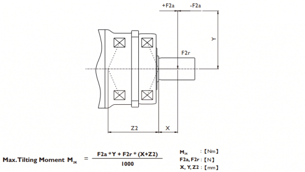
| MF060 | MF075 | MF100 | MF140 | MF180 | MF210 | MF240 | |
| Z2 [mm] | 41.3 | 50.1 | 58.9 | 72.7 | 93.7 | 98.5 | 112.2 |
Applied to the output shaft center at 100 rpm.
| Model No. | MF060 | MF075 | MF100 | MF140 | MF180 | MF210 | MF240 | ||||||||
| Ø(1) | Stage | 1 | 2 | 1 | 2 | 1 | 2 | 1 | 2 | 1 | 2 | 1 | 2 | 1 | 2 |
| 8 | kg.cm2 | - | 0.10 | - | - | - | - | - | - | - | - | - | - | - | - |
| 11 | 0.21 | 0.16 | - | 0.17 | - | - | - | - | - | - | - | - | - | - | |
| 14 | 0.24 | 0.20 | 0.54 | 0.21 | - | 0.42 | - | - | - | - | - | - | - | - | |
| 19 | 0.64 | - | 0.79 | 0.60 | 2.51 | 0.66 | - | 1.83 | - | - | - | - | - | - | |
| 24 | - | - | 4.06 | - | 4.78 | 3.94 | 6.85 | 4.11 | - | 4.61 | - | - | - | - | |
| 28 | - | - | - | - | 6.15 | - | 8.38 | 5.48 | - | 6.14 | - | - | - | - | |
| 32 | - | - | - | - | 8.03 | - | 10.41 | 7.36 | 19.50 | 8.17 | - | 10.55 | - | - | |
| 35 | - | - | - | - | 14.72 | - | 15.56 | 14.04 | 26.71 | 15.54 | 39.60 | 17.75 | 86.48 | 20.80 | |
| 38 | - | - | - | - | 17.38 | - | 20.43 | 16.71 | 29.11 | 18.19 | 42.43 | 20.17 | 86.48 | 23.66 | |
| 42 | - | - | - | - | - | - | 25.44 | - | 34.35 | 23.20 | 47.65 | 25.4 | 92.61 | 28.88 | |
| 48 | - | - | - | - | - | - | 54.66 | - | 64.13 | 52.42 | 77.41 | 55.18 | 122.26 | 58.64 | |
| 55 | - | - | - | - | - | - | - | - | 97.45 | - | 111.26 | - | 156.7 | 92.48 | |
| 60 | - | - | - | - | - | - | - | - | - | - | - | - | 180.17 | - | |
(1) Ø = Input shaft diameter.
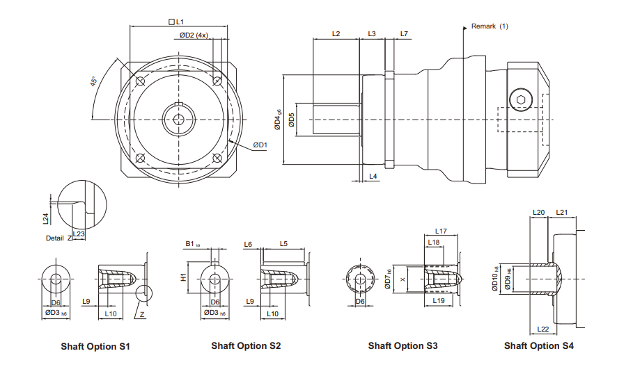
| MF060 | MF075 | MF100 | MF140 | MF180 | MF210 | MF240 | |
| D1 | 68 | 85 | 120 | 165 | 215 | 250 | 290 |
| D2 | 5.5 | 7 | 9 | 11 | 13.5 | 17 | 17 |
| D3 h6 | 16 | 22 | 32 | 40 | 55 | 75 | 85 |
| D4 g6 | 60 | 70 | 90 | 130 | 160 | 180 | 200 |
| D5 | 18.5 | 25.8 | 36.8 | 55.2 | 69.2 | 82.2 | 92.2 |
| D6 | M5 x 0.8P | M8 x 1.25P | M12 x 1.75P | M16 x 2P | M20 x 2.5P | M20 x 2.5P | M20 x 2.5P |
| D7 h6 | 16 | 22 | 32 | 40 | 55 | 75 | 85 |
| D9 H6 | 15 | 20 | 30 | 40 | 55 | - | - |
| D10 h8 | 18 | 24 | 36 | 50 | 68 | - | - |
| L1 | 62 | 76 | 101 | 141 | 182 | 215 | 245 |
| L2 | 28 | 36 | 58 | 82 | 82 | 105 | 130 |
| L3 | 20 | 20 | 30 | 30 | 30 | 38 | 40 |
| L4 | 2 | 2.5 | 3 | 3 | 3 | 3 | 3 |
| L5 | 25 | 32 | 50 | 63 | 70 | 90 | 125 |
| L6 | 2 | 2 | 4 | 5 | 6 | 7 | 3 |
| L7 | 6 | 7 | 10 | 12 | 15 | 17 | 22 |
| L9 | 4.8 | 7.2 | 10 | 12 | 15 | 15 | 15 |
| L10 | 12.5 | 19 | 28 | 36 | 42 | 42 | 42 |
| L17 | 26 | 26 | 26 | 40 | 41.5 | 52 | 60 |
| L18 | 15 | 15 | 15 | 20 | 21.5 | 28 | 36 |
| L19 | 21 | 22.5 | 23 | 33.5 | 33.5 | 45 | 53 |
| L20 | 12 | 14 | 18 | 22 | 23 | - | - |
| L21 | 22 | 22 | 32 | 33 | 32 | - | - |
| L22 | 19 | 21 | 25 | 30 | 30 | - | - |
| L23 | 2 | 2.5 | 2.5 | 2.5 | 2.5 | 2.5 | 4 |
| L24 | 0.3 | 0.4 | 0.4 | 0.4 | 0.4 | 0.4 | 0.5 |
| B1 h9 | 5 | 6 | 10 | 12 | 16 | 20 | 22 |
| H1 | 18 | 24.5 | 35 | 43 | 59 | 79.5 | 90 |
| X DIN5480 | W16 x 0.8 x 30 x 18 x 6m | W22 x 1.25 x 30 x 16 x 6m | W32 x 1.25 x 30 x 24 x 6m | W40 x 2 x 30 x 18 x 6m | W55 x 2 x 30 x 26 x 6m | W70 x 2 x 30 x 34 x 6m | W80 x 2 x 30 x 38 x 6m |
(1) Dimensions are related to motor interface. Please contact APEX for details.
Need help with your application? Our specialists are happy to use their years of experience to assist you in selecting the right products.