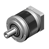
PEII series
- Steel housing and output shaft
- Output shaft with key
- Ratio 3 to 100
- Torque 10 Nm – 459 Nm
- Black coated steel housing, aluminum output and motor adapter flange
- Steel output shaft with key
- Spur gear design
- Nominal torques:
- T2N : 10 Nm - 459 Nm
- Ratios
- 1-stage : 3 / 4 / 5 / 7 / 10
- 2-stage : 12 / 15 / 16 / 20 / 25 / 30 / 35 / 40 / 50 / 70 / 100
- Low backlash
- 1-stage : ≤ 6 ~ 8 arcmin
- 2-stage : ≤ 8 ~ 10 arcmin
- High efficiency
- 1-stage : ≥ 97%
- 2-stage : ≥ 94%
- Easy mount
- Compact structure
- Sizes available: PEII 050 / PEII 070 / PEII 090 / PEII 120 / PEII 155
- Also available with an input shaft, please contact Apex Dynamics for more information
PEII |
Stage | Ratio(1) | PEII 050 | PEII 070 | PEII 090 | PEII 120 | PEII 155 | |
|
Nominal output torque 2N |
Nm |
1 |
3 | 16 | 42 | 110 | 217 | 430 |
| 4 | 16 | 42 | 113 | 223 | 440 | |||
| 5 | 15 | 40 | 118 | 220 | 435 | |||
| 7 | 12 | 35 | 96 | 198 | 366 | |||
| 10 | 10 | 27 | 68 | 155 | 295 | |||
|
2 |
12 | 16 | 42 | 110 | 217 | 430 | ||
| 15 | 15 | 40 | 109 | 213 | 424 | |||
| 16 | 16 | 42 | 116 | 228 | 452 | |||
| 20 | 16 | 42 | 116 | 230 | 454 | |||
| 25 | 15 | 40 | 123 | 228 | 450 | |||
| 30 | 15 | 40 | 108 | 212 | 422 | |||
| 35 | 12 | 35 | 100 | 206 | 382 | |||
| 40 | 16 | 43 | 117 | 232 | 459 | |||
| 50 | 15 | 40 | 123 | 228 | 450 | |||
| 70 | 12 | 35 | 100 | 206 | 382 | |||
| 100 | 10 | 27 | 70 | 162 | 308 | |||
| Emergency stop torque T2NOT | Nm | 1,2 | 3~100 | 3 times nominal output torque T2N | ||||
| Max. Acceleration torque T2B | Nm | 1,2 | 3~100 | T2B = 60% of T2NOT | ||||
| No load running torque (2) | Nm | 1 | 3~10 | 0,05 | 0,1 | 0,4 | 0,8 | 2,5 |
| 2 | 12~100 | 0,05 | 0,1 | 0,3 | 0,4 | 0,8 | ||
| Backlash (3) | arcmin | 1 | 3~10 | ≤ 8 | ≤ 7 | ≤ 6 | ≤ 6 | ≤ 6 |
| 2 | 12~100 | ≤ 10 | ≤ 9 | ≤ 8 | ≤ 8 | ≤ 8 | ||
| Torsional rigidity | Nm/arcmin | 1,2 | 3~100 | 0,9 | 2,2 | 8 | 12 | 16 |
| Nominal input speed n1N | rpm | 1,2 | 3~100 | 4.500 | 4.000 | 3.600 | 3.600 | 2.500 |
| Max. input speed n1B | rpm | 1,2 | 3~100 | 8.000 | 6.000 | 6.000 | 4.800 | 3.600 |
| Max. radial load F2rB (4) | N | 1,2 | 3~100 | 810 | 1.150 | 1.530 | 3.260 | 4.550 |
| Max. axial load F2aB (4) | N | 1,2 | 3~100 | 405 | 575 | 765 | 1.630 | 2.275 |
| Max. tilting moment M2k | Nm | 1,2 | 3~100 | 15 | 35 | 55 | 170 | 300 |
| Operating temperature | °C | 1,2 | 3~100 | 0° C ~ +90°C | ||||
| Degree of Protection | 1,2 | 3~100 | IP65 | |||||
| Lubrication | 1,2 | 3~100 | Synthetisch lubrication grease | |||||
| Mounting position | 1,2 | 3~100 | All directions | |||||
| Running noise (2) | dB (A) | 1,2 | 3~100 | ≤ 60 | ≤ 62 | ≤ 64 | ≤ 66 | ≤ 68 |
| Max. bending moment based on input flange Mb (5) | Nm | 1,2 | 3~100 | 5 | 12 | 22 | 45 | 54 |
| Efficiency n | % | 1 | 3~10 | ≥ 97% | ||||
| 2 | 12~100 | ≥ 94% | ||||||
- Ratio ( i = N in / N out )
- These values are measured by gearbox with ratio 10 (1-stage) or ratio 100 (2-stage) at 3.000 rpm no loading.
By lower ratio and/or higher RPM, the noise level could be 3 to 5 dB higher - Backlash is measured at 2% of Nominal output torque T2N.
- Applied to the ourput flange center at 100 rpm.
- Max. motor weight* (kg) = (0.1 x Mb) / (motor length (m))
*with symmetrically distributed motor weight
*with horizontal and stationary mounting
Permitted Radial And Axial Loads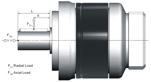
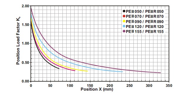 If radial force F2r is not exerted on the center of the ouput shaft X < ½ x L or X > ½ x L, the permitted radial and axial loads can be calculated by the position load factor Kb on the above diagram.
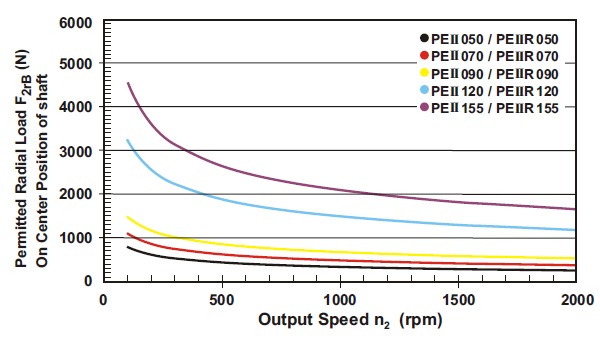 Permitted radial load F2r on center of output shaft X = ½ x L for various output speeds.(A) Ø Input shaft diameter
(B) Permitted loading values on the output shaft. Please contact Apex Dynamics for more details.
| Model No. | PEII 050 | PEII 070 | PEII 090 | PEII 120 | PEII 155 | ||||||
| Ø (A) (C3) | 1-Stage | 2-Stage | 1-Stage | 2-Stage | 1-Stage | 2-Stage | 1-Stage | 2-Stage | 1-Stage | 2-Stage | |
| 8 | kg*cm2 | 0.10 | 0.10 | 0.12 | 0.10 | - | - | - | - | - | - |
| 11 | 0.16 | 0.16 | 0.19 | 0.16 | - | - | - | - | - | - | |
| 14 | 0.20 | 0.20 | 0.22 | 0.20 | 0.36 | 0.24 | - | - | - | - | |
| 19 | - | - | 1.53 | 1.51 | 1.70 | 1.58 | 2.20 | 1.73 | - | 2.18 | |
| 24 | - | - | - | - | 2.24 | 2.12 | 2.74 | 2.27 | 4.52 | 2.73 | |
| 28 | - | - | - | - | 2.68 | 2.55 | 3.17 | 2.70 | 4.94 | 3.15 | |
| 32 | - | - | - | - | - | - | 7.77 | 7.30 | 9.70 | 7.91 | |
| 35 | - | - | - | - | - | - | 10.80 | 10.30 | 12.80 | 11.00 | |
| 38 | - | - | - | - | - | - | 14.00 | 13.50 | 16.00 | 14.20 | |
| 42 | - | - | - | - | - | - | - | - | 24.50 | - | |
(A) ø = Input shaft diameter
PEII series:
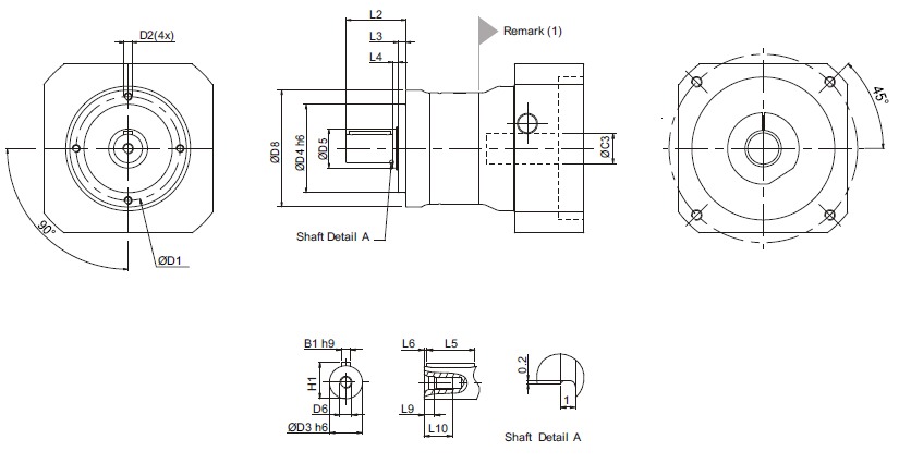
| Dimensions | PEII 050 | PEII 070 | PEII 090 | PEII 120 | PEII 155 | |||||
| 1-stage | 2-stage | 1-stage | 2-stage | 1-stage | 2-stage | 1-stage | 2-stage | 1-stage | 2-stage | |
| D1 | 44 | 62 | 80 | 108 | 140 | |||||
| D2 | M4 x 9 | M5 x 10 | M6 x 12 | M8 x 15 | M10 x 18 | |||||
| D3 h6 | 12 | 16 | 22 | 32 | 40 | |||||
| D4 h6 | 35 | 52 | 68 | 90 | 120 | |||||
| D5 | 17 | 22 | 30 | 40 | 55 | |||||
| D6 | M4 x 0.7P | M5 x 0.8P | M8 x 1.25P | M12 x 1.75P | M16 x 2P | |||||
| D8 | 50 | 70 | 90 | 120 | 155 | |||||
| L2 | 24.5 | 36 | 46 | 70 | 97 | |||||
| L3 | 4 | 4.5 | 6 | 7 | 9.5 | |||||
| L4 | 2.5 | 3.5 | 4 | 5 | 5.5 | |||||
| L5 | 14 | 25 | 32 | 50 | 70 | |||||
| L6 | 2 | 2 | 2 | 4 | 6 | |||||
| L9 | 4.5 | 4.8 | 7.2 | 10 | 12 | |||||
| L10 | 10 | 12.5 | 19 | 28 | 36 | |||||
| B1 h9 | 4 | 5 | 6 | 10 | 12 | |||||
| H1 | 13.5 | 18 | 24.5 | 35 | 43 | |||||
(1) Dimensions are related to motor interface. Please contact Apex Dynamics for details.
(2) For input shaft dimensions please contact Apex Dynamics for details
Need help with your application? Our specialists are happy to use their years of experience to assist you in selecting the right products.