KF-S1 spiral bevel series
- Steel housing and output shaft
- Output shaft smooth
- Ratio 1:1 and 2:1 (spiral bevel)
- Torque 24 – 1300 Nm
- Black coated steel housing, aluminum output and motor adapter flange
- Steel output shaft, smooth
- Spiral bevel gear design
- Nominal torques:
- T2N : 24 Nm - 1.300 Nm
- Ratios
- 1-stage : 1 / 2
- Low backlash
- 1-stage : ≤ 3 arcmin
- High efficiency
- 1-stage : ≥ 97%
- Easy mount
- High accuracy
- The output shaft rotates in the same direction as the servomotor
- Available sizes: KF060 / KF075 / KF100 / KF140 / KF180 / KF210 / KF240
| KF | Stage | Ratio(1) | KF 060 |
KF 075 |
KF 100 |
KF 140 |
KF 180 |
KF 210 |
KF 240 |
|
|
Nominal output torque T2N
|
Nm
|
1 | 1 | 25 | 45 | 78 | 150 | 360 | 585 | 1,300 |
| 2 | 24 | 42 | 68 | 150 | 330 | 544 | 1,220 | |||
| Emergency stop torque T2NOT | Nm | 1 | 1 | 2 times of nominal torque T2N | ||||||
| Max. Acceleration torque T2B | Nm | 1 | 1~2 | 1,5 times of nominal torque T2N | ||||||
| No load running torque (2) | Nm | 1 | 1~2 | 0.3 | 0.3 | 1.5 | 1.7 | 5.5 | 9 | 20 |
| Backlash (3) | arcmin | 1 | 1~2 | ≤3 | ≤3 | ≤3 | ≤3 | ≤3 | ≤3 | ≤3 |
| Torsional rigidity | Nm/arcmin | 1 | 1~2 | 0.8 | 3.5 | 9 | 20.5 | 44 | 80 | 168 |
| Nominal input speed n1N | rpm | 1 | 1~2 | 6,500 | 4,500 | 3,500 | 2,000 | 1,500 | 1,200 | 1,000 |
| Max. input speed n1B | rpm | 1 | 1~2 | 7.500 | 6,500 | 5,500 | 4,500 | 3,500 | 3,000 | 2,200 |
| Max. radial load F2rB (4) | N | 1 | 1~2 | 5,400 | 7,700 | 11,100 | 15,100 | 26,100 | 36,400 | 46,900 |
| Max. axial load F2aB (4) | N | 1 | 1~2 | 2,700 | 3,850 | 5,550 | 9,050 | 14,550 | 18,200 | 23,450 |
| Max. tilting moment M2k | Nm | 1 | 1~2 | 390 | 630 | 1,100 | 2,230 | 5,020 | 6,430 | 10,810 |
| Operating temperature | °C | 1 | 1~2 | 0° C ~ +90°C | ||||||
| Degree of Protection | 1 | 1~2 | IP65 | |||||||
| Lubrication | 1 | 1~2 | Synthetisch lubrication grease | |||||||
| Mounting position | 1 | 1~2 | All directions | |||||||
| Running noise (5) | dB (A) | 1 | 1~2 | ≤68 | ≤70 | ≤74 | ≤76 | ≤77 | ≤78 | ≤80 |
| Efficiency n | % | 1 | 1~2 | ≥97% | ||||||
- Overbrengverhouding ( i = N in / N out ) Ratio ( i = N in / N out )
- Backlash is measured at 2% of Nominal output torque T2N
- These values are measured by gearbox with ratio = 2 (1-stage) at 3.000 rpm without load.
- Applied to the ourput flange center at 100 rpm.
- These values are measured by gearbox with ratio = 2 (1-stage) at 3,000 rpm no loading.
By lower ratio and/or higher RPM, the noise level could be 3 to 5 dB higher.
Maximum tilting moment::


| Size | KF060 | KF075 | KF100 | KF140 | KF180 | KF210 | KF240 | |
| Z2 (mm) | 104.4 | 119.3 | 144.3 | 178 | 251.9 | 253.9 | 330.8 | |
- Applied to the ourput flange center at 100 rpm.
Maximum radial and axial loads:

The maximum radial and axial loads on the output shaft of the gearbox depends on the design of the gearbox supporting bearings.
Apex Dynamics uses the extension straddle oversized ball bearing design. This can take heavy load from both axles

Permitted radial load F2r on center of output shaft X = ½ x L for various output speeds.

If radial force F2r is not exerted on the center of the ouput shaft X < ½ x L or X > ½ x L, the permitted radial and axial loads can be calculated by the position load factor Kb on the above diagram.
| Model No. | KF 060 |
KF 075 |
KF 100 |
KF 140 |
KF 180 |
KF 210 |
KF 240 |
|
| Ø (A) (C3) | 1-stage | 1-stage | 1-stage | 1-stage | 1-stage | 1-stage | 1-stage | |
| 8 | kg*cm2 | 0.10 | - | - | - | - | - | - |
| 11 | 0.17 | 0.18 | - | - | - | - | - | |
| 14 | 0.21 | 0.50 | - | - | - | - | - | |
| 19 | 0.62 | 0.63 | 1.69 | - | - | - | - | |
| 24 | - | 4.49 | 4.89 | 5.05 | - | - | - | |
| 28 | - | - | 6.14 | 6.55 | - | - | - | |
| 32 | - | - | 8.54 | 9.47 | 10.18 | - | - | |
| 35 | - | - | 13.86 | 14.91 | 15.21 | 15.68 | 23.46 | |
| 38 | - | - | 18.87 | 20.69 | 20.7 | 21.69 | 23.46 | |
| 42 | - | - | - | 22.58 | 22.83 | 23.59 | 25.28 | |
| 48 | - | - | - | 55.45 | 58.45 | 25.40 | 61.61 | |
| 55 | - | - | - | - | - | 61.02 | 89.67 | |
| 60 | - | - | - | - | - | - | 112.49 | |
(A) Ø Input shaft diameter
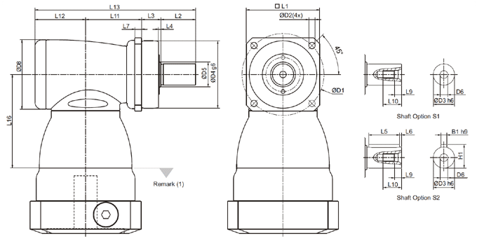
KF-S1 / S2 -spiral bevel:
| KF 060 | KF 075 | KF 100 | KF 140 | KF 180 | KF 210 | KF 240 | |
| 1-stage | 1-stage | 1-stage | 1-stage | 1-stage | 1-stage | 1-stage | |
| D1 | 68 | 85 | 120 | 165 | 215 | 250 | 290 |
| D2 | 5.5 | 6.6 | 9 | 11 | 13.5 | 17 | 17 |
| D3 h6 | 16 | 22 | 32 | 40 | 55 | 75 | 85 |
| D4 g6 | 60 | 70 | 90 | 130 | 160 | 180 | 200 |
| D5 | 18.5 | 25.8 | 36.8 | 55.2 | 69.2 | 82.2 | 92.2 |
| D6 | M5x0.8P | M8x1.25P | M12x1.75P | M16x2P | M20x2.5P | M20x2.5P | M20x2.5P |
| D8 | 64 | 72 | 92 | 116 | 156 | 195 | 240 |
| L1 | 62 | 76 | 101 | 141 | 182 | 215 | 245 |
| L2 | 28 | 36 | 58 | 82 | 82 | 105 | 130 |
| L3 | 20 | 20 | 30 | 30 | 30 | 38 | 40 |
| L4 | 2 | 2.5 | 3 | 3 | 3 | 3 | 3 |
| L5 | 25 | 32 | 50 | 63 | 70 | 90 | 125 |
| L6 | 2 | 2 | 4 | 5 | 6 | 7 | 3 |
| L7 | 6 | 7 | 10 | 12 | 15 | 17 | 20 |
| L9 | 4.8 | 7.2 | 10 | 12 | 15 | 15 | 15 |
| L10 | 12.5 | 19 | 28 | 36 | 42 | 42 | 42 |
| L11 | 50 | 58 | 67.5 | 88 | 127 | 131.5 | 169 |
| L12 | 46.5 | 52.5 | 61.5 | 76 | 97.5 | 105.5 | 141 |
| L13 | 144.5 | 166.5 | 217 | 276 | 336.5 | 380 | 480 |
| L16 | 81.5 | 97 | 113.5 | 147.5 | 196.5 | 229 | 260 |
| B1 h9 | 5 | 6 | 10 | 12 | 16 | 20 | 22 |
| H1 | 18 | 24.5 | 35 | 43 | 59 | 79.5 | 90 |
(1) Dimensions are related to motor interface. Please contact Apex Dynamics for details.
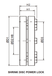
| Model No. | Dimension | D1 | D2 | D3 | H1 | H2 | Screw(1) | Ta (2) | J | Order Code |
| No. x type | (Nm) | (kg.CM2) | ||||||||
| KF 060 | SSD-d18xdw15 | 44 | 18 | 30 | 15 | 18.5 | 5 x M5 | 4 | 0.4 | SSD-18 |
| KF 075 | SSD-d24xdw20 | 50 | 24 | 36 | 19.5 | 23 | 6 x M5 | 4 | 0.8 | SSD-24 |
| KF 100 | SSD-d36xdw30 | 72 | 36 | 52 | 23.5 | 27.5 | 5 x M6 | 12 | 3.9 | SSD-36 |
| KF 140 | SSD-d50xdw40 | 90 | 50 | 70 | 27.5 | 31.5 | 8 x M6 | 12 | 11.2 | SSD-50 |
| KF 180 | SSD-d68xdw55 | 115 | 68 | 86 | 30.5 | 34.5 | 10 x M6 | 12 | 30.9 | SSD-68 |
- 10.9 Class, DIN 931
- Tightening Torque
Need help with your application? Our specialists are happy to use their years of experience to assist you in selecting the right products.